


62 PARAGON II USER MANUAL
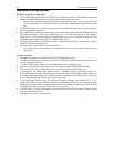
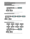
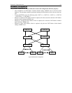
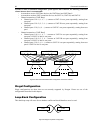
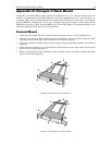
In order to make a redundant configuration system operate more efficient, the following connection
scheme between tiers is recommended:
− Assume there are two UMT Base devices, the UMT-Base1 and UMT-Base2
− Assume there are three UMT second tier devices, the UMT-2A, UMT-2B, and UMT-2C
− Channel connection of UMT-Base1
Channel ports 3*N+1 (1, 4, 7….) connect to UMT-2A user ports sequentially, starting from
user port 1
Channel ports 3*N+2 (2, 5, 8….) connect to UMT-2B user ports sequentially, starting from
user port 1
Channel ports 3*N (3, 6, 9….) connect to UMT-2C user ports sequentially, starting from user
port 1
− Channel connection of UMT-Base2
Channel ports 3*N+1 (1, 4, 7….) connect to UMT-2A user port sequentially, starting from
user port 9 if UMT-2A has 16 user ports.
Channel ports 3*N+2 (2, 5, 8….) connect to UMT-2B user port sequentially, starting from
user port 9 if UMT-2A has 16 user ports.
Channel ports 3*N (3, 6, 9….) connect to UMT-2C user port sequentially, starting from user
port 9 if UMT-2A has 16 user ports.
Figure 57 Recommended Redundant Configuration connection scheme
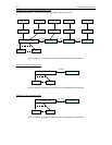
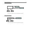
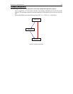
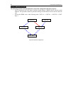
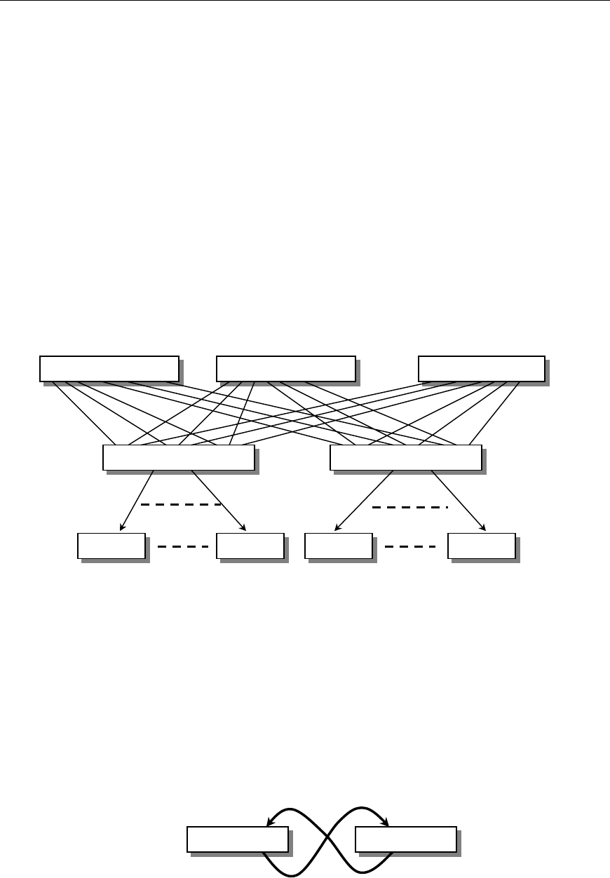
Illegal Configuration
Illegal configurations are those that are not currently supported by Paragon. Please use one of the
configurations described in this chapter.
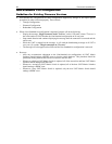
Loop-Back Configuration
This dead-loop setup will cause Server database conflict and should therefore never be used.
Figure 58 Illegal Loop-Back Configuration
UMT UMT
UMT-2A UMT-2B
UMT-Base1
UMT-2C
UMT-Base2
UST UST UST UST