


32185/32186/32192/32195/32196 Group
Starter Kit User’s Manual M3A-2154G52B
REJ10B0223-0140/Rev.1.40 Jan. 2007 Page 42 of 79
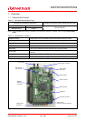
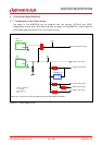
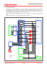
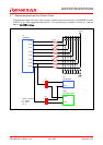
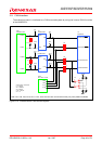
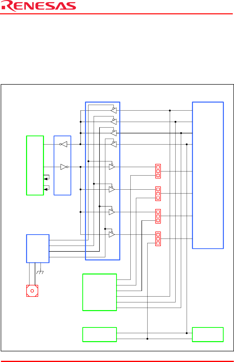
2.4 Serial I/O Interface
The evaluation board is interfaced to the host PC (Windows) through its RS-232C by using SIO of
the M32R/ECU. Of the RS-232C control signals, only TXD and RXD are used for connection to the
host PC (Windows). The unused CTS and RTS are directly-coupled to configure a loop-back. The
unused DSR and DTR also are configured in a similar manner.
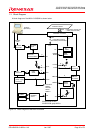
The serial I/O interface is configured in such a way that only one serial I/O channel can be used at a
time.
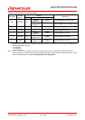
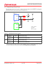
Any of the four channels 0–3 can be selected using a rotary switch.
A
TXD
RXD
RXD0
RXD1
RXD2
RXD3
TXD0
TXD1
TXD2
TXD3
P82/TXD0/TO26
P85/TXD1/TO23
P174/TXD2/TO28
P83/RXD0/
TO25
3
1
2
J15
2
J18
P86/RXD1/TO22
2
J19
P175/RXD2/TO27
J20
P75/RTDRXD/
RXD3/NBDD1
3
1
2
3
1
3
1
U1
M32R/ECU
P74/RTDTXD/
TXD3/NBDD0
TXD
RXD
DSR
DTR
RTS
CTS
P83
P175
P86
P82
P174
P85
P74
P75
NBDD0
NBDD1
Y1
Y0
Y2
Y3
CB
U9
MAX3232CSE+
CN5
XM2C-0912
U8
QS21X384Q1G
U7
TC74VHC138FT
CN4
XG4C-1434
SW2
DR-KR10H
CON2
FX1-144S-1.27DS
CON1
FX1-144S-1.27DS
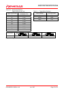
* CNx,CONx : Connector
* Jx : Jumper
* SWx : Switch
* Ux : IC
Figure 2.4 Serial I/O Interface