


32185/32186/32192/32195/32196 Group
Starter Kit User’s Manual M3A-2154G52B
REJ10B0223-0140/Rev.1.40 Jan. 2007 Page 43 of 79
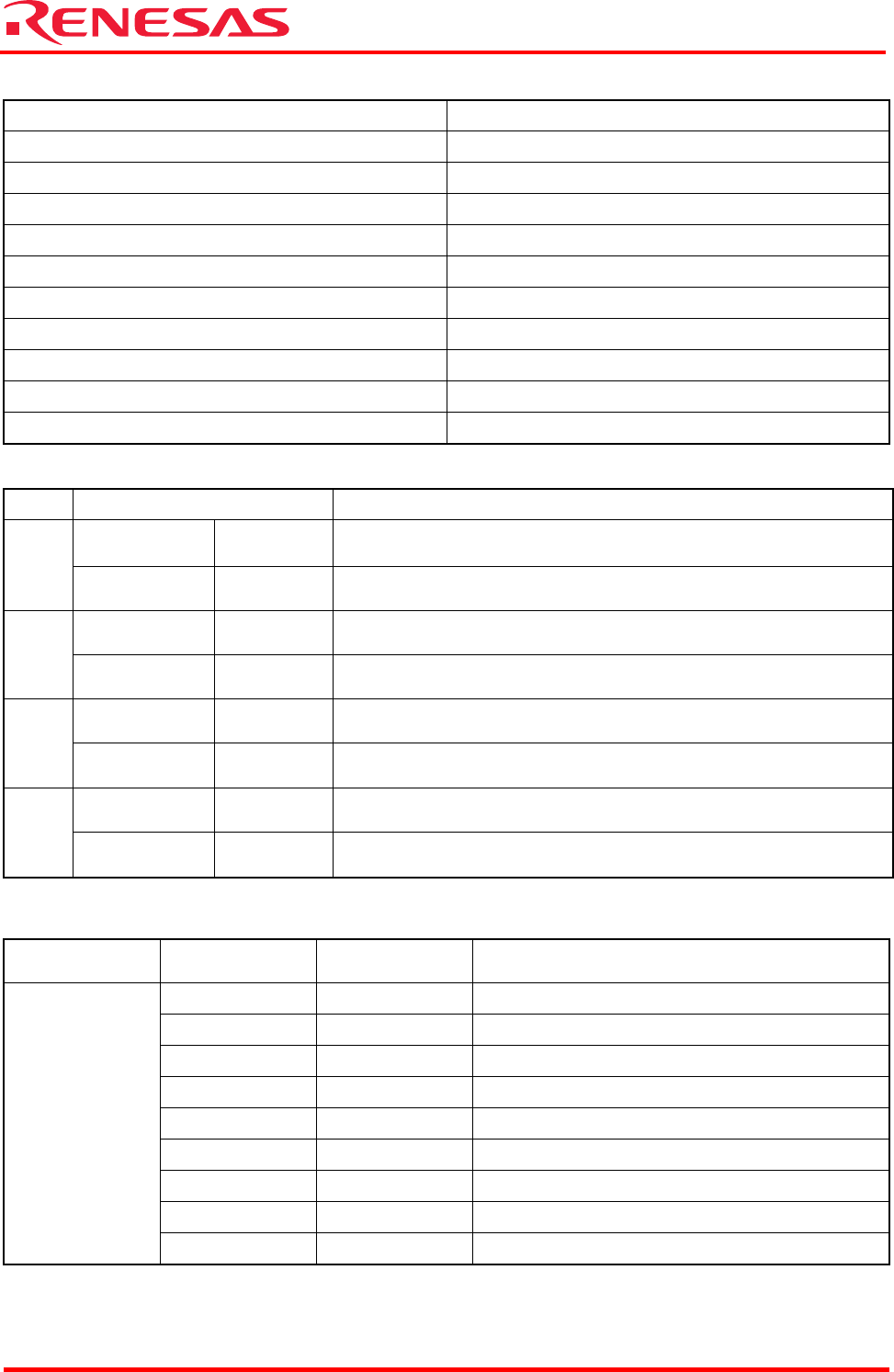
Table 2.5 Channel Selection by a Rotary Switch
Rotary switch position SIO Selected channel
0 SIO0
1 SIO1
2 SIO2
3 SIO3
4 SIO0
5 SIO1
6 SIO2
7 SIO3
8 SIO0
9 SIO1
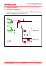
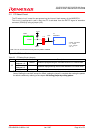
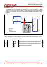
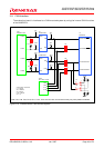
Table 2.6 Serial I/O Interface (Jumper)
Name Condition Description
Shorted
between 1–2
Default Connects P83/RXD0/TO25 to the extension connector (CON2)
J15
Shorted
between 2–3
Uses the RXD0 function in RS-232C
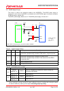
Shorted
between 1–2
Default Connects P86/RXD1/TO22 to the extension connector (CON2)
J18
Shorted
between 2–3
Uses the RXD1 function in RS-232C
Shorted
between 1–2
Default Connects P175/RXD2/TO27 to the extension connector (CON2)
J19
Shorted
between 2–3
Uses the RXD2 function in RS-232C
Shorted
between 1–2
Default
Connects P75/RTDRXD/RXD3/NBDD1 to the extension connector
(CON1)
J20
Shorted
between 2–3
Uses the RXD3 function in RS-232C
Note: The jumpers J15, J18, J19 and J20 are shorted by jumper parts.
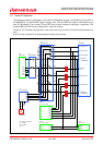
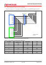
Table 2.7 RS-232C Connector Pin Assignments
Connector
Name
Pin No Signal Name Description
1 DCD Unused
2 RXD Received data
3 TXD Transmitted data
4 DTR Connects to the DSR pin
5 SG Ground
6 DSR Connects to the DTR pin
7 RTS Connects to the CTS pin
8 CTS Connects to the RTS pin
CN5
9 RI Unused