


32185/32186/32192/32195/32196 Group
Starter Kit User’s Manual M3A-2154G52B
REJ10B0223-0140/Rev.1.40 Jan. 2007 Page 78 of 79
3.8 Setting Jumper by Cutting Pattern
Some jumpers are shorted at default condition by pattern wiring on the reverse side of printed
circuit board. Case of setting the condition except for default, the following setting is required.
Note: Case that the printed circuit board is cut pattern by user, the product is except from repairable list.
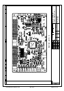
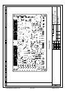
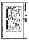
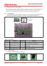
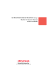
3.8.1 Cutting Pattern
The pattern wiring for default condition of jumper is on the reverse side of printed circuit board.
After checking the position of the jumper, cut the pattern wiring between through-holes
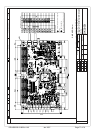
Figure 3.4 Example of Cutting Pattern
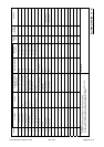
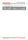
Table 3.6 List of Jumper
Jumper No. Description Jumper No. Description
J2 Sets MOD1 to 0 J7 Power supply from VCCE
J3 Power supply from VCCE J8
Controls MOD0 by EXTMOD0, unless control
MOD0 by EXTMOD0 sets MOD0 to 0
J4 Power supply from VCCE J10
Enables reprogramming the mounted M32R/ECU’s
internal flash
J5 Power supply from VCCE J12 Uses the VR control (VOL0)
J6 Power supply from AVCC0 J13 Uses the VR control (VOL1)
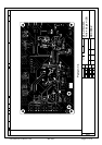
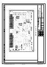
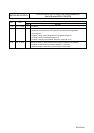
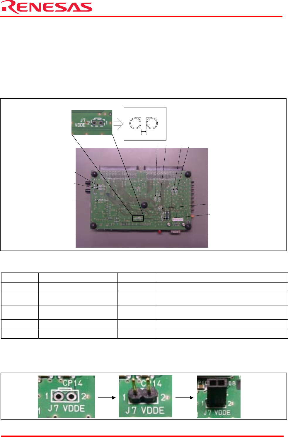
3.8.2 Jumper Shorting
The jumper is shorted according to the condition.
The example of using jumper pin is shown below.
Figure 3.5 Example of Using Jumper Pin
Note: Cut pattern wiring
from edge of
through-hole.
Example of cutting
pattern
Zoom (J7)
J12
J13
J3
J8 J10
J5 J6
J4
J2
About 0.5mm