


32185/32186/32192/32195/32196 Group
Starter Kit User’s Manual M3A-2154G52B
REJ10B0223-0140/Rev.1.40 Jan. 2007 Page 50 of 79
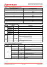
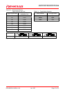
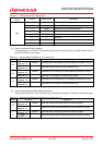
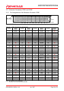
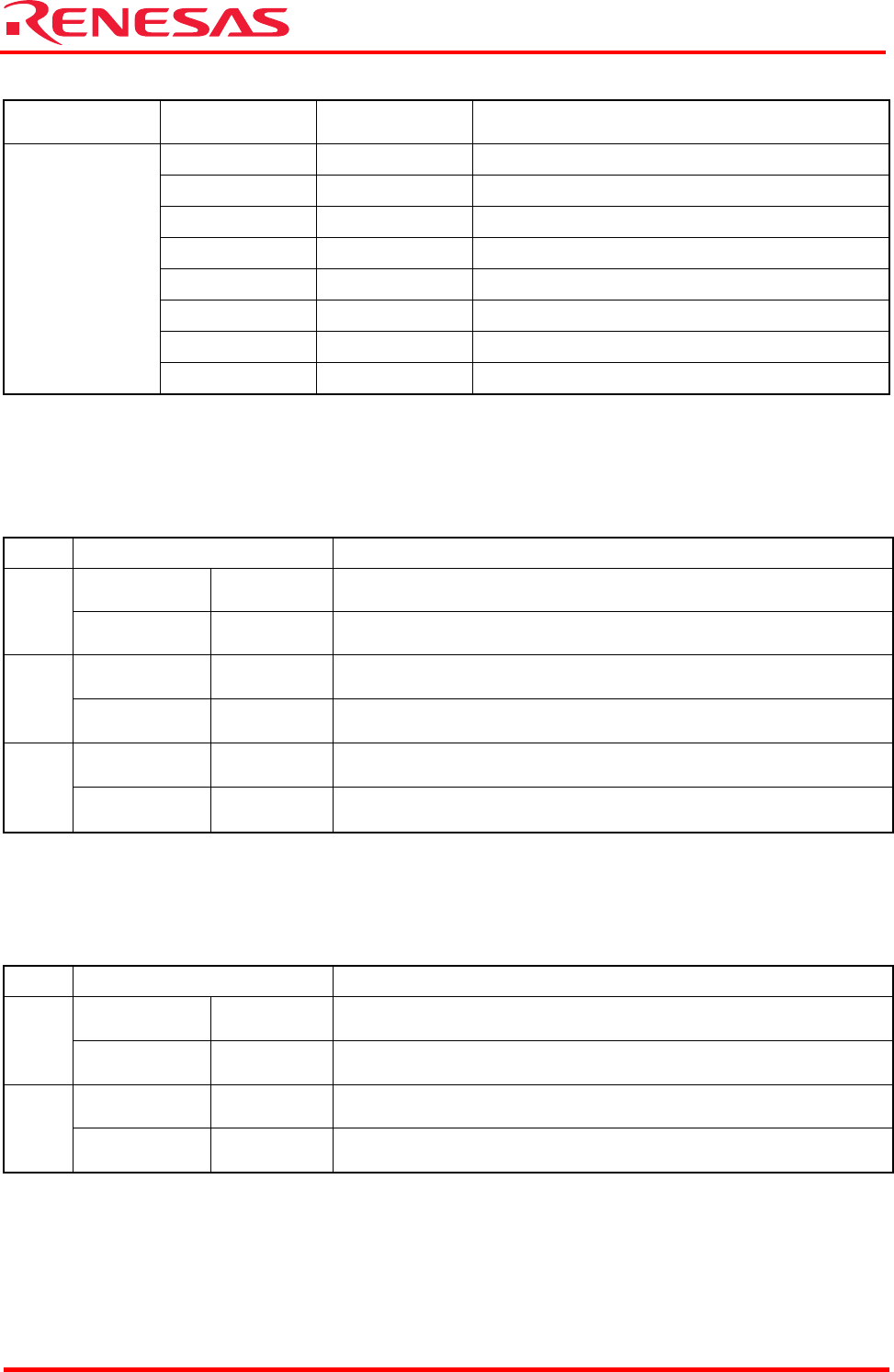
Table 2.13 CAN Connector Pin Assignments
Connector
Name
Pin No Signal Name Description
1 CANH1 High-level CAN0 input/output port
2 CANL1 Low-level CAN0 input/output port
3 CANH2 High-level CAN1 input/output port
4 CANL2 Low-level CAN1 input/output port
5 GND Ground
6 — Unused
7 GND Ground
CN3
8 — Unused
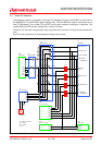
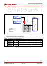
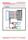
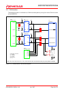
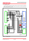
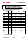
(1) How to connect the CAN connector
The jumpers J14, J16 and J17 allow selecting the destinations to which the CAN communication
pins (CTX, CRX) are connected.
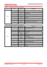
Table 2.14 Jumper Usage Conditions (J14, J16 and J17)
Name Condition Description
Shorted
between 1–2
Default Connects P221/CRX0/HREQ to the extension connector (CON1)
J14
Shorted
between 2–3
Uses the CRX0 function in CAN connector CN3
Shorted
between 1–2
Default Connects P137/TIN23/CTX1 to the extension connector (CON1)
J16
Shorted
between 2–3
Uses the CTX1 function in CAN connector CN3
Shorted
between 1–2
Default Connects P136/TIN22/CRX1 to the extension connector (CON1)
J17
Shorted
between 2–3
Uses the CRX1 function in CAN connector CN3
Note: The jumpers J14, J16 and J17 are shorted by jumper parts.
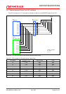
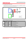
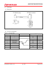
(2) How to select the terminating resistor connection
The jumpers J9 and J11 allow the terminating resistors to be used in the CAN transmission path.
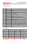
Table 2.15 Selecting the Terminating Resistor Connection (J9, J11)
Name Condition Description
Shorted
between 1–2
Default Uses the CAN0 terminating resistor mounted on-board
J9
Open
between 1–2
Does not use the CAN0 terminating resistor mounted on-board
Shorted
between 1–2
Default Uses the CAN1 terminating resistor mounted on-board
J11
Open
between 1–2
Does not use the CAN1 terminating resistor mounted on-board
Note: The jumpers J9 and J11 are shorted by jumper parts.