


6
Notes:
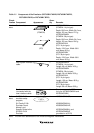
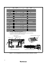
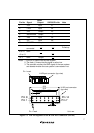
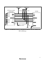
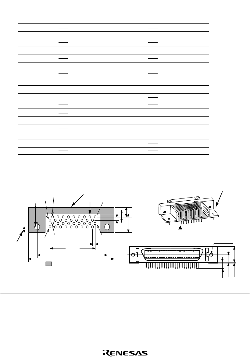
H-UDI port connector
(Pin 1 mark)
(top view)
Unit: mm
4.8
M2.6 x 0.45
9.0
0.3
3.9
H-UDI port connector (front view)
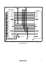
1. Input to or output from the user system.
2. The slash (/) means that the signal is active-low.
3. The emulator monitors the GND signal of the user system and detects
whether or not the user system is connected.
Pin
No.
Signal
Input/
Output
Note
/AUDSYNC
AUDCK
NC
NC
TCK
GND
AU DATA 0
GND
AU DATA 1
GND
GND
GND
GND
GND
GND
GND
AU DATA 2
AU DATA 3
NC
TMS
/RESETP
GND
NC
GND
/TRST
GND
TDI
GND
GND
GND
GND
GND
GND
GND
TDO
/ASEBRKAK
User reset
Output
Output
Input
Input
Input
Input
Output
Output
Output
Output
Output
Output
Output
Output
1
2
3
4
5
6
7
8
9
10
11
12
13
14
15
16
17
18
19
20
21
22
23
24
25
26
27
28
29
30
31
32
33
34
35
36
Pin
No.
Signal
Input/
Output
Note
*1
*1
*2
*2
*2
*3
SH7630
Pin No.
86
85
87
90
91
92
27
28
24
26
25
7
141
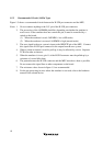
: Pattern inhibited area
Edge of the board
(connected to the connector)
0.7
+0.1
0
φ
2
1.27
1
3
4.5
1.1
1.905
9.0
21.59
37.61
43.51
36
35
4
2.8
+0.2
0
φ
4.09
H-UDI port connector (top view)
SH7630
Pin No.
*2
Pulled-up
Figure 1.2 Pin Arrangement of the H-UDI Port Connector (36 Pins)