


6
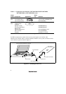
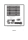
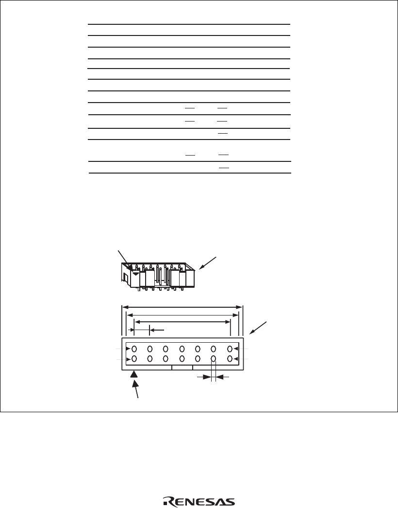
Pin 1 mark
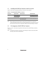
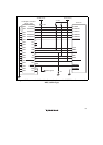
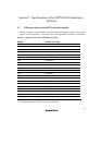
Notes:
1. Input to or output from the user system.
2. The slash (/) means that the signal is active-low.
3. The emulator monitors the GND signal of the user
system and detects whether or not the user system
is connected.
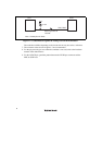
25.0
23.0
6 x 2.54 = 15.24
(2.54)
0.45
Pin 1
Pin 8
Pin 7
Pin 14
Pin 1 mark
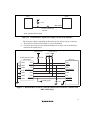
H-UDI port connector
(top view)
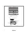
H-UDI port connector
(top view)
Pin No. Signal
1
2
3
4
5
6
7
8
9
11
10, 12,
and 13
14
TCK
/TRST
TDO
/ASEBRKAK
TMS
TDI
/RESETP
N.C.
(GND)
UVCC
GND
Input/
Output*
1
*2
*2
*2
GND
*3
Output
Input
Input
Output
Output
Input
Input
I/O
Output
Note
User reset
*4
*5
SH7710
Pin No.
202
201
200
203
199
198
215
Unit: mm
Figure 1.3 Pin Assignments of the H-UDI Port Connector (14 Pins)