


10
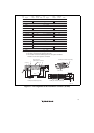
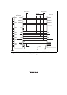
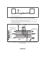
1.5.2 Recommended Circuit (14-Pin Type)
Figure 1.7 shows a recommended circuit between the H-UDI port connector and the MPU.
Notes: 1. Do not connect anything to the N.C. pins of the H-UDI port connector.
2. The processing of the /ASEMD0 pin differs depending on whether the emulator is
used or not. As the emulator does not control this pin, it must be controlled by a
switch on the board.
(1) When the emulator is used: /ASEMD0 = low
(2) When the emulator is not used: /ASEMD0 = high
3. The reset signal in the user system is input to the /RESETP pin (pin 215) of the MPU.
Connect this signal to the H-UDI port connector as the output from the user system.
4. When a network resistance is used for pull-up, it may be affected by a noise. Separate
TCK from other resistances.
5. The pattern between the H-UDI connector and the MPU must be as short as possible.
Do not connect the signal lines to other components on the board.
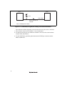
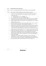
6. When the power of the emulator is turned on (make sure that the emulator is inserted
into the host computer and the power supply is turned on), and the target system (such
as the system mounting the target device) is connected to the emulator (the power
supply of the board is turned off), the power-supply voltage of the target device (target
system) may become higher around 1.2 V to 1.4 V than the normal voltage due to the
leakage current from the emulator. This is because TMS and TRST are driven to high
by the emulator; the leakage current occurs from a TMS line before starting the
emulator software (HDI or HEW), and from TMS and TRST lines through the CPU
after starting the emulator software. This phenomenon only occurs in the SuperH
TM
family E10A emulator.
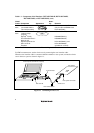
Although the CPU will not be degraded or damaged, a power-on reset may be
disabled. The power-supply voltage raised by the leakage current can be reduced to
0.2 V by inserting a diode in the output pins (TMS and TRST) of the emulator. For the
type (type number) and the inserting direction of the diode, see figure 1.6.