


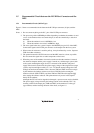

11
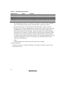
CPU
3.3 V
4.7 kΩ
E10A
TMS, TRST
Diode equivalent to
1SS106*
Note: Schottky-barrier diode
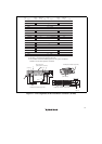
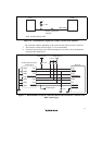
Figure 1.6 Countermeasure against the Leakage Current in the Emulator
The result above differs depending on the circuit and can only be used as a reference.
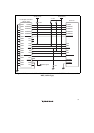
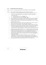
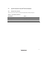
7. The resistance values shown in figure 1.7 are recommended.
8. For the pin processing in cases where the emulator is not used, refer to the hardware
manual of the related device.
1
TCK
TMS
N.C.
TDO
TDI
GND
GND
GND
GND
GND
GND
2
3
4
5
6
7
8
9
11
10
12
13
14
H-UDI port connector
(14-pin type)
SH7710
Reset signal
4.7 kΩ
RESET
1 kΩ
4.7 kΩ
ASEBRKAK
TRST
TCK
RESETP
TMS
TDO
TDI
TRST
ASEBRKAK
ASEMD0
VccQ (3.3 V)
VccQ (3.3 V)
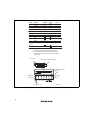
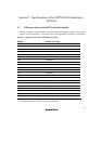
Figure 1.7 Recommended Circuit for Connection between the H-UDI Port Connector and
MPU (14-Pin Type)