


( 17 / 52 )
(2) Name of Each Part of Emulator
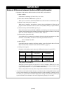
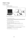
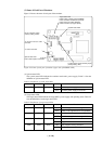
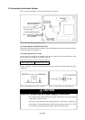
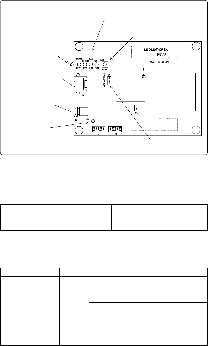
Figure 2.2 shows the name of each part of the emulator.
Figure 2.2 Name of each part of emulator (upper side of M30620T-CPE)
(1) System status LED
The system status LED indicates the emulator main unit's power supply. Table 2.1 lists the
definition of system status LED.
Table 2.1 Definition of system status LED
(2) Target status LED
The target status LEDs indicate the target MCU's power supply and operating status. Table 2.2
lists the definition of each target status LED.
Table 2.2 Definition of target status LEDs
Name
POWER
Number
LED1
Color
Orange
Status
ON
OFF
Function
Emulator power supply is turned on.
Emulator power supply is turned off.
Name
POWER
CLOCK
RESET
RUN
Number
LED2
LED3
LED4
LED5
Color
Orange
Green
Red
Green
Status
ON
OFF
ON
OFF
ON
OFF
ON
OFF
Function
Power is supplied from the target MCU.
Power is not supplied from the target MCU.
Clock X
IN or XCIN is supplied to the target MCU.
Clock is not supplied to the target MCU.
Target MCU is reset.
Target MCU is not reset.
User program is being executed.
User program has been halted.
Target status LED
LED2: Power of target system (POWER)
LED3: Oscillation of XIN/XCIN (CLOCK)
LED4: Reset pin of MCU (RESET)
LED5: Execution of program (RUN)
System reset switch
P87/XCIN selection switch
(Factory-setting: PORT)
J2: Serial interface cable
connector
J1: Power connector
System status LED
LED1: State of power of emulator
J1: MCU power supply selection jumper
(Factory-setting: INT)