


( 37 / 52 )
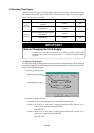
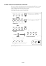
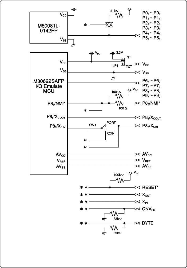
Figure 4.2 Connection diagram (emulation circuits)
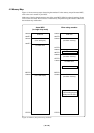
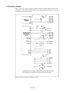
4.4 Connection Diagram
Figure 4.2 shows the connection diagram of M30620T-CPE. This connection diagram mainly shows
the interface section, and the circuits which are not connected to the target system such as the
emulator's control system are omitted.
** : These signals are connected to an MCU via the internal circuit of the emulator.
* : These signals are connected to the internal circuit of the emulator.