


( 19 / 52 )
2.2 Starting Up the Emulator
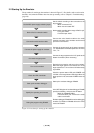
The procedure for starting up the emulator is shown in Figure 2.3. For details, refer to each section
hereafter. And, when the emulator does not start up normally, refer to "Chapter 5. Troubleshooting"
(page 40).
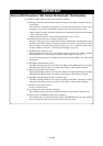
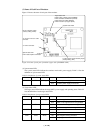
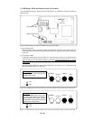
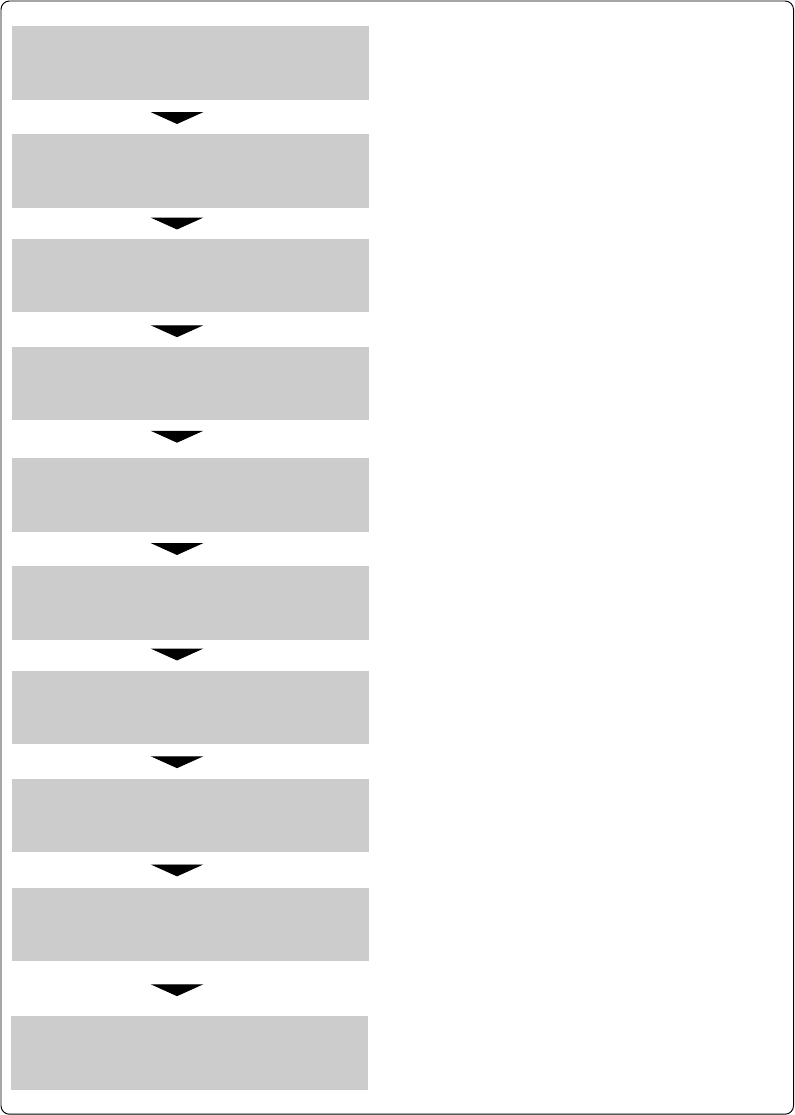
Figure 2.3 Procedure for starting up the emulator
Set the switch according to the connection to the
target system.
- When connected: INT
- When not connected: EXT
Set the switch according to the usage of P87/XCIN pin.
- For a port: PORT
- For XCIN input: XCIN
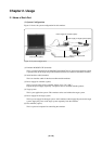
Connect the serial interface cable to the serial
interface connector (J2) of emulator and the serial
port of the host machine.
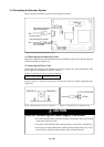
Connect the power supply to the power connector
(J1). Specifications of emulator power are: DC 4.5 to
7.0 V, 1 A.
Connect the target system to the LCC probe at the
bottom of emulator (when necessary).
Recheck the connection, and turn on the emulator.
When the target system is connected, turn on the
target system too. Turn on them as simultaneously
as possible.
Check the system status LED and "POWER" and
"CLOCK" of the target status LEDs light. When the
target system is not connected "POWER" does not
light.
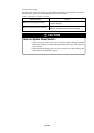
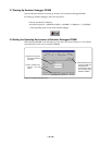
Start up the emulator debugger PD30M.
In the INIT dialog box of emulator debugger PD30M,
specify the following, and press the OK button.
- MCU file: "M30620C.MCU"
- Communication port: Port that the serial
cable is connected
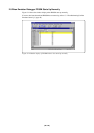
Emulator debugger PD30M offers various debugging
functions. For details on PD30M, refer to the online
manual of PD30M.
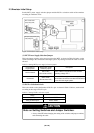
Set the MCU power supply selection jumper.
Set the P8
7/XCIN selection switch.
Connect the serial interface cable.
Connect the power supply for emulator.
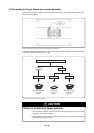
Connect the target system.
Turn on the emulator.
Check the LED of emulator.
Start up the emulator debugger.
Specify the operating environment.
Debug the program using PD30M.