


M306V8T-EPB User’s Manual 2. Setup
REJ10J0777-0100 Rev.1.00 2005.08.01 Page 34 of 90
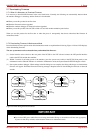
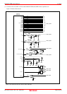
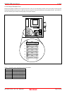
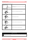
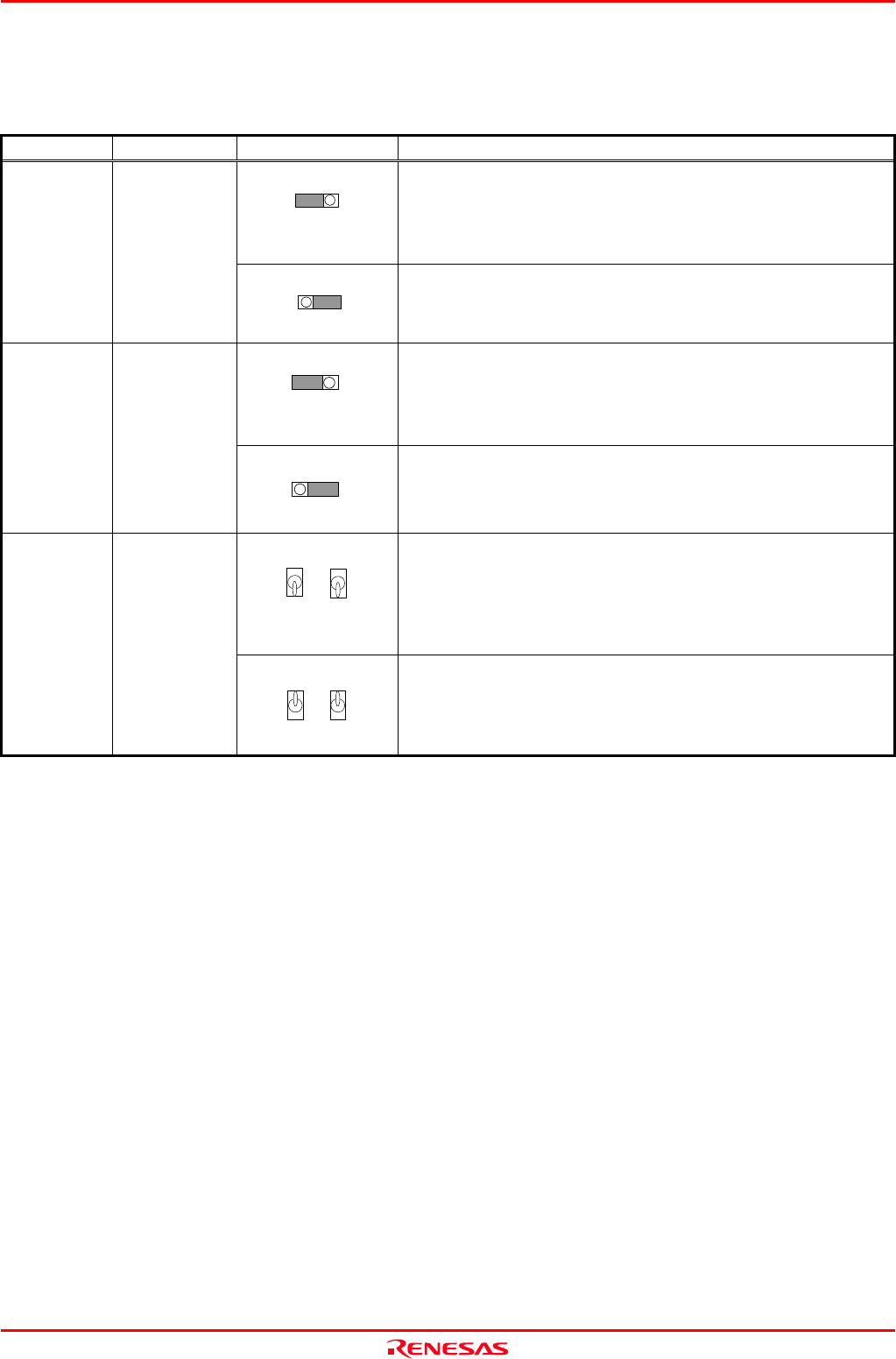
(1) Setting JP2, JP3, SW1 to SW5 on the M306V8T-EPB
Tables 2.1 and 2.2 show the settings of JP2, JP3, SW1 to SW5 on the M306V8T-EPB.
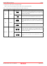
Table 2.1 Switch settings of the M306V8T-EPB (JP2, JP3, SW1 to SW5) (1/2)
Switch
Switch name Setting Description
1 2 3
●EPB TRGT
(Factory-setting)
Connects pin VCC3 of the evaluation MCU to the internal power
supply of the M306V8T-EPB. When the user system is not
connected, use this setting.
JP2 VCC3
1 2 3
●EPB TRGT
Connects pin VCC3 of the evaluation MCU to the user system.
1 2 3
●EPB TRGT
(Factory-setting)
Connects pin CNVSS2 of the evaluation MCU to GND in the
M306V8T-EPB. When the user system is not connected, use this
setting.
JP3 CNVSS2
1 2 3
●EPB TRGT
Connects pin CNVSS2 of the evaluation MCU to the user system.
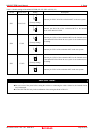
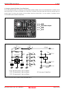
●EPB TRGT
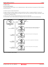
SW1
OSC1
●EPB TRGT
SW2
OSC2
(Factory-setting)
Connects pins OSC1 and OSC2 of the evaluation MCU to the
internal circuit of the M306V8T-EPB. When the user system is not
connected, use this setting
SW1,SW2 OSC1,OSC2
●EPB TRGT
SW1
OSC1
●EPB TRGT
SW2
OSC2
Connects pins OSC1 and OSC2 of the evaluation MCU to the user
system.