


M306V8T-EPB User’s Manual 4. Hardware Specifications
REJ10J0777-0100 Rev.1.00 2005.08.01 Page 80 of 90
IMPORTANT
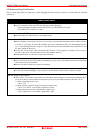
Notes on Internal Flash ROM of the MCU:
In single-chip mode and memory expansion modes, this product downloads a user program to the flash ROM of
an MCU. By checking "Debug Option" in the MCU tab of the MCU setting dialog box of the emulator
debugger, you can disable the operation of the internal flash ROM of the MCU to use the emulation memory.
The maximum operating frequencies are as follows.
(1) "Debug Option " unchecked
Access area: Flash ROM of MCU
Max. operating frequency: 16 MHz (0 wait, 1 wait)
(2) "Debug Option " checked
Access area: Emulation memory of the PC7501
Max. operating frequency: 10 MHz (0 wait, 1 wait)
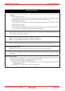
Because the number of write/erase cycles of the internal flash ROM of the MCU is limited, it must be replaced
at the end of its service-life.
If the following errors occur frequently when downloading a program, replace the MCU board.
(1) Flash ROM erase error occurred ERROR (16258)
(2) Flash ROM verify error occurred ERROR (16259)
To purchase products for replacement, contact your local distributor.
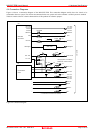
Note on Memory Area Expansion Function (Normal Mode):
During debugging in memory expansion mode or microprocessor mode with this product, the emulation
memory can be allocated. The emulation memory can be specified up to 4 areas by 4 MB in the MAP tab of the
MCU setting dialog box of the emulator debugger.
Each maximum operating frequency is as follows.
- Maximum operating frequency (at 3.3 V) 0 wait: 6 Hz
1 wait to 3 wait: 16 MHz
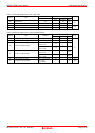
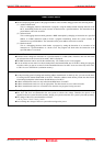
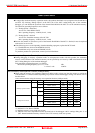
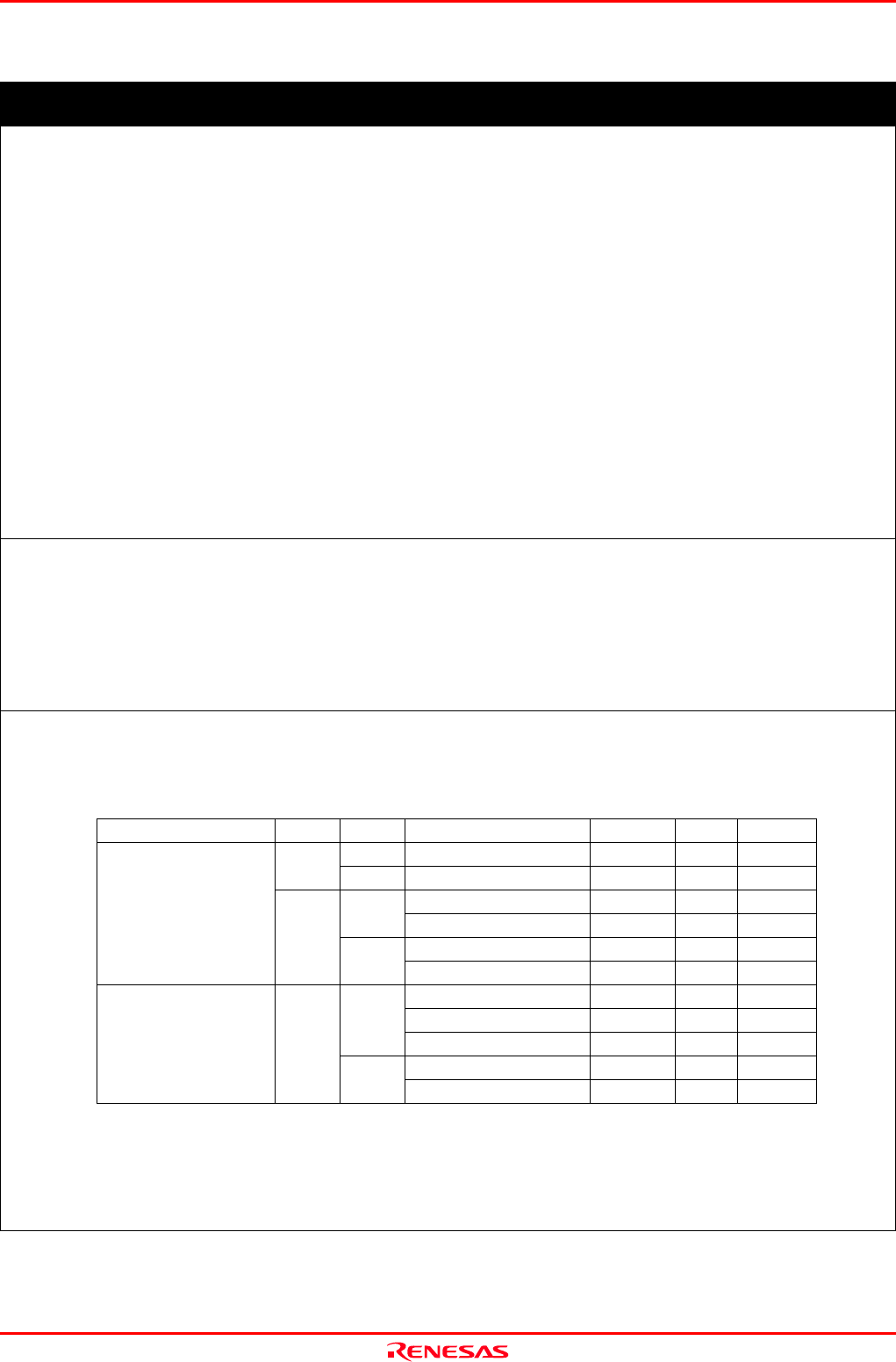
Note on Memory Area Expansion Function (4-MByte Mode):
When using the memory area expansion function (4-Mbyte mode), please note that the memory to which the
evaluation MCU is connected differs depending on processor modes and debugger settings. For details, refer to
the table below.
Areas connected when using the memory area expansion function (4-Mbyte mode)
Processor mode PM13
*1
OFS
*2
Accessed area of target MCU Banks 0--5 Bank 6 Bank 7
0
50000h--7FFFFh
EXT
*3
EXT MAP
*4
1
1
50000h--7FFFFh
EXT EXT MAP
50000h--7FFFFh
EXT EXT MAP
0
80000h--BFFFFh
EXT EXT MAP
50000h--7FFFFh
EXT EXT MAP
Memory expansion mode
0
1
80000h--BFFFFh
EXT MAP ---
50000h--7FFFFh
EXT EXT MAP
80000h--BFFFFh
EXT EXT ---
0
C0000h--FFFFFh
--- --- MAP
50000h--7FFFFh
EXT EXT MAP
Microprocessor mode ---
1
80000h--BFFFFh
EXT MAP ---
*1: Indicates bit 3 at address 00005h.
*2: Indicates bit 2 at address 0000Bh.
*3: Indicates memory access in the user system.
*4: Indicates area access dependent on how the MAP tab of the debugger’s MCU settings dialog box is set
(INT: internal emulation memory of the PC7501, EXT: memory in the user system).