


OVERVIEW
4
Vista KVM-Series Installation and Operations Manual
System overview
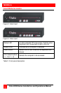
The Vista KVM-series switch is designed to provide seamless, trouble-free
switching from a single KVM station to any connected CPU. You can
switch to the connected computers by simple keyboard commands or
using the front panel buttons.
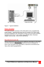
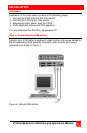
Figure 1 shows a typical configuration using the Vista 4 port switch with
DB25 connectors. Up to 4 CPUs can be connected to the Vista 4 port
switch and accessed from a single KVM station.
KVM station
A KVM station, consisting of a keyboard, video monitor and mouse,
connects directly to the Vista switches’ KVM connectors. The KVM station
can switch its keyboard, video monitor and mouse to any of the connected
CPUs and fully control that CPU if authorized. Files and folders can be
managed, applications can be executed, upgrades can be performed and
general maintenance done from the KVM station.
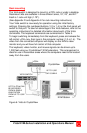
The keyboard, video monitor and mouse used for the KVM station should
be compatible with all of the CPU that will be connected. The KVM stations
mouse must be a PS/2 mouse. The Vista switch will translate PS/2 mouse
movements and present it in serial form to computers that use a serial
mouse The KVM connectors on the Vista switch are HD15F for the video
monitor and MiniDin-6F for the keyboard and mouse.
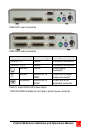
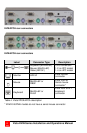
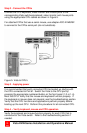
CPU connections
The CPU connectors on the Vista switch depend on the model ordered.
The “U” model connectors are DB25F for each CPU. The “PC” model
connectors are HD15F (video) and MiniDin-6F (keyboard and mouse) for
each CPU. Attached CPUs that use a serial mouse, use adapter ACC-
KVM6F9F to connect to the CPUs serial port (do not substitute).