


Installation
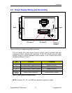
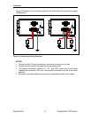
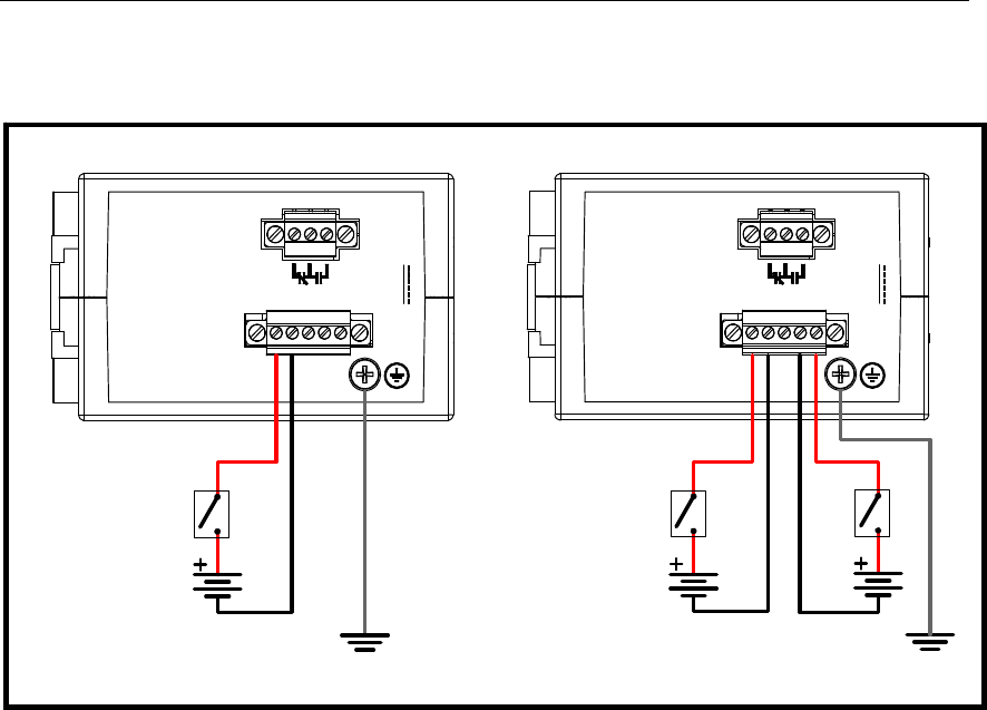
Figure 6 illustrates the connections required for both single and dual power supply
configurations:
Ratings:
12-24V,
, 2A
Figure 6: Power Supply Wiring Examples
NOTES:
• Connect to the DC inputs according to the polarity markings on the unit.
• Chassis Ground must be connected to the protective earth.
• The internal connection between P1-. P2-, and GND means that if two power
supplies are connected to the unit, their negative terminals must be at the same
potential.
• Equipment must be installed according to the applicable country wiring codes.
P1+
P1-
GND
P2-
P2+
Ratings:
12-24V,
, 2A
P1+
P1-
GND
P2-
P2+
RuggedCom® 12 RuggedSwitch™i800 family