


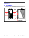
Installation
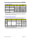
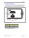
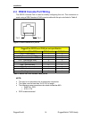
2.4 RS232 Console Port Wiring
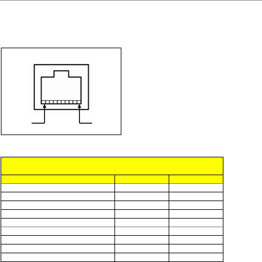
The RS232 Console Port is used for initially configuring the unit. The connection is
made using a DB9-Female to RJ45 console cable with the pin-outs listed in Table 5.
Pin 1 Pin 8
Figure 8: RS232 Female DCE pin-out
RuggedCom RS232 over RJ45 pin-out specification
Signal Name (PC is DTE) DB9- Female RJ45 Male
DCD – Carrier detect 1 2
RxD – Receive data (to DTE) 2 5
TxD – Transmit data (from DTE) 3 6
DTR – Data terminal ready 4 3
Signal GND 5 4
DSR – Data set ready 6 1*
RTS – Ready to send 7 8
CTS – Clear to send 8 7
RI – Ring Indicator 9 1*
Table 5: RS232 over RJ45 console cable pin-out
NOTE:
• This port is not intended to be a permanent connection
• The cable must be less than 2m (6.5 ft) in length.
• The following cross-connections are made inside the i800:
o DSR / RI / DTR
o RTS / CTS
• DCD is not connected.
RuggedCom® 14 RuggedSwitch™i800 family