


Product Overview
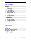
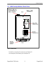
1.3 i800 Family Front Panel View
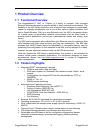
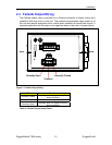
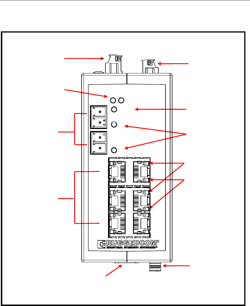
Figure 1: Front Panel
The front panel shown is representative of the i800 family. Note that there are
several Ethernet options available in several models, outlined in Section 1.3.2,
below.
Fail-Safe
Relay
Power LEDs
Power Connecto
r
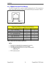
RS-232
Console Port
Ports 1 – 4/6/8:
10/100 BaseTx
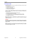
Memory Slot
Ports 5-7, 7&8, or 9:
10/100/1000Base Tx,
100FX, 1000SX/LX
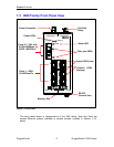
Alarm LED
Fiber port LEDs
Speed LEDs (top)
Power 1
Power 2
i802
Link/Act LEDs
(bottom)
3
1
4
2
56
7
8
Alarm
R
RuggedCom® 6 RuggedSwitch™i800 family