


Product Overview
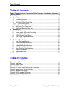
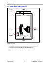
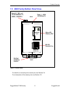
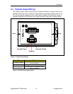
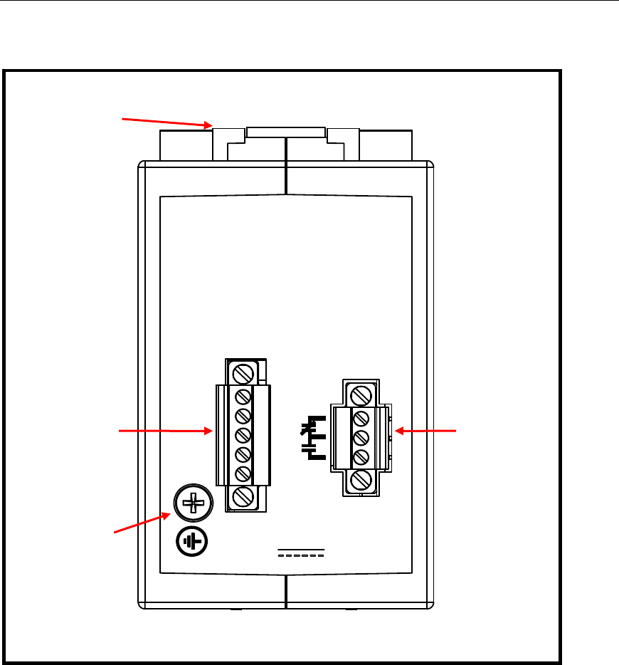
1.4 i800 Family Top Panel View
Figure 2: Top Panel
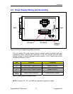
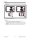
For details on connecting the power supplies and Ground, see Section 2.2.
For details on connecting the Fail-Safe Relay, see Section 2.3
Ratings:
12-24V ,
, 2A
P1+
P1-
GND
P2-
P2+
Fail-Safe
Relay
Power
Connecto
r
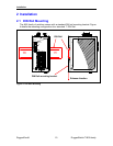
back
front
DIN Rail
mounting
bracket
Chassis
Ground
RuggedCom® 8 RuggedSwitch™i800 family