


10
2008 RuggedCom Inc. All rights reserved Rev104
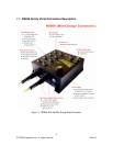
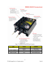
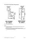
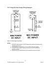
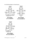
The RS969 family has 2 different power supply input connectors---Mini A-coded male connector or
M23 A-code male connector shown in Figure 2.2.1.1. The Mini power connector only has 4
terminals, so only one power supply source is allowed to connect to the RS969 with Mini power
connector; The M23 power connector has 5 terminal pins which means 2 power supply sources are
allowed to power the RS969 with M23 power connector.
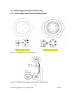
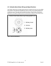
The RS969 family supports dual redundant power supplies – “Power Supply 1 (PS1)” and “Power
Supply 2 (PS2)”. The connections for PS1, PS2 are shown in Table1 and 2.
Refer to
Table 1 and 2 for a description of each terminal and sections 2.3.2 through 2.3.4 for wiring
examples.
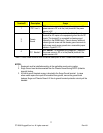
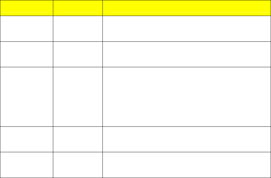
Terminal # Description Usage
1 PS1 Live / +
PS1 Live / + is connected to the positive (+) terminal if the
power source is DC or to the (Live) terminal if the power
source is AC.
2 PS1 Neutral / -
PS1 Neutral / - is connected to the negative (-) terminal if
the power source is DC or to the (Neutral) terminal if the
power source is AC.
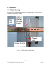
3
Chassis
Ground
Chassis Ground is connected to the Safety Ground
terminal for AC inputs or the equipment ground bus for DC
inputs. This terminal 3 is connected to chassis ground
internally in the RS969 family. There is also an additional
chassis ground screw and the chassis ground connects to
both power supply surge grounds via a removable jumper
shown in Figure 2.2.1.2 .
4
PS2 Live / +
PS2 Live / + is connected to the positive (+) terminal if the
power source is DC or to the (Live) terminal if the power
source is AC.
5
PS2 Neutral / -
PS2 Neutral / - is connected to the negative (-) terminal if
the power source is DC or to the (Neutral) terminal if the
power source is AC.
Table 1: RS969 Power terminal block connection description for M23 A-code male connector