


4.2 Power Supply Wiring and Grounding
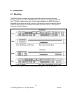
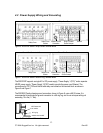
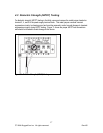
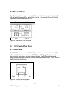
Figure 6: RSG2000 Series Philips Screw Terminal Block
Philips Screw Terminal without CoverPhilips Screw Terminal with Cover
Safety Cover
Safety Cover
Screws
Chassis Ground
Connection
Surge / Chassis
Ground Jumper
Terminal
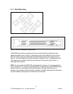
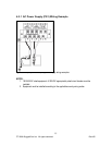
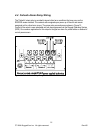
Figure 7: RSG2000 Series Phoenix Plug Terminal Block
Phoenix Plug Terminal without CoverPhoenix Plug Terminal with Cover
Safety Cover
Screws
Safety Cover
Chassis Ground
Connection
Terminal
Surge / Chassis
Ground Jumper
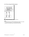
The RSG2100P supports a single AC or DC power supply, “Power Supply 1 (PS1)” and a separate
48VDC power supply, “Power Supply 2 (PS2)” used to provide the power over Ethernet. The
connections for PS1, PS2 and the fail-safe relay are located on the terminal block as shown in
Figure 6 and Figure 7.
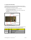
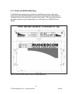
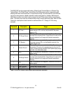
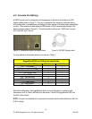
The RSG2000 Family chassis ground connection, shown in Figure 8, uses a #6-32 screw. It is
recommended to terminate the ground connection in a #6 ring lug, and to use a torque setting not
exceeding 15 in.lbs (1.7 Nm).
Figure 8: Chassis Ground Connection
#6 rin
g
lu
g
stainless steel standoff
#6-32 screw with
ext. washer.
13
© 2008 RuggedCom Inc. All rights reserved Rev105