


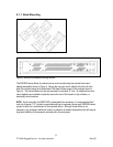
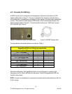
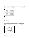
4.5 Console Port Wiring
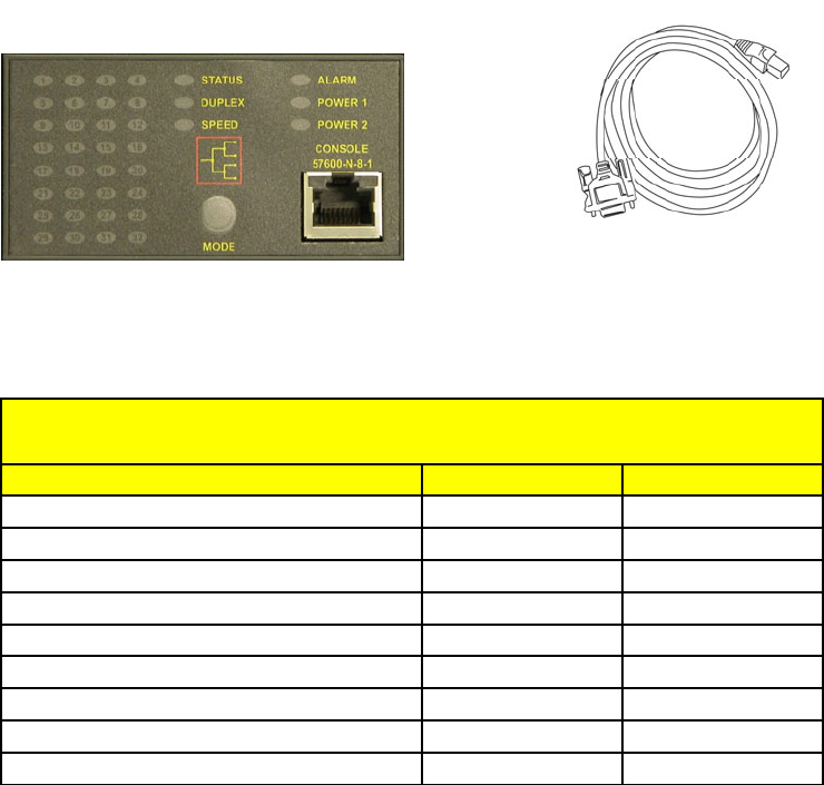
A RS232 console port for configuration and management of the device is located on the LED
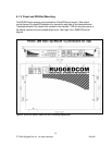
display module shown in Figure 13. This port is intended to be a temporary connection during
initial configuration or troubleshooting and allows for direct access to the serial-based management
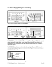
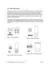
console. The connection is made using the DB9-Female to RJ45 console cable included in the
device packaging shown in Figure 14. Console connection settings are: 57600 baud, no parity
bits, 8 data bits, and 1 stop bit.
Figure 13: Console port location on display board Figure 14: RSG200 Console cable
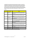
For user reference, the console cable pin-out is show in Table 5.
RuggedCom RS232 over RJ45 pin-out specification
Si
g
nal Name
(
PC is DTE
)
DB9- Female RJ45 Male
DCD
–
Carrier detect 1 2
RxD
–
Receive data
(
to DTE
)
25
TxD
–
Transmit data
(
from DTE
)
36
DTR
–
Data terminal read
y
43
Si
g
nal GND 5 4
DSR
–
Data set read
y
61*
RTS
–
Read
y
to send 7 8
CTS
–
Clear to send 8 7
RI
–
Rin
g
Indicator 9 1*
Table 4: RS232 over RJ45 console cable pin-out
After initial configuration, the RuggedSwitch device can be configured via a number of new
mechanisms such as Telnet, and the built-in web server. Consult the RuggedSwitch ROS User
Guide for further details.
NOTE: This port is not intended to be a permanent connection and the cable shall be less than 2m
(6.5 ft) in length.
19
© 2008 RuggedCom Inc. All rights reserved Rev105