


1 Table of Figures
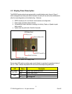
Figure 1: RSG2000 Series LED Display Panel ................................................................................ 8
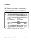
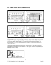
Figure 2: RSG2000 Series Rack mount chassis orientation options – Front and rear mount..........10
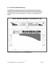
Figure 3: RSG2000 Series 19” Rack Mount Adapters.....................................................................11
Figure 4: Rack mount adapter mounting location............................................................................11
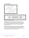
Figure 5: RSG2000 Series PANEL/DIN RAIL mounting diagram with ............................................12
Figure 6: RSG2000 Series Philips Screw Terminal Block ...............................................................13
Figure 7: RSG2000 Series Phoenix Plug Terminal Block................................................................13
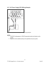
Figure 8: AC (PS1) & 48VDC (PS2) power supply wiring examples ...............................................15
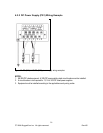
Figure 9: DC (PS1) & 48VDC (PS2) power supply wiring examples ...............................................16
Figure 10: Dielectric Strength (HIPOT) Testing...............................................................................17
Figure 11: Failsafe Alarm Relay Wiring...........................................................................................18
Figure 12: Console port location on display board ..........................................................................19
Figure 13: RSG200 Console cable..................................................................................................19
Figure 14: Ethernet panel LED description......................................................................................20
Figure 15: RJ45 port pins configuration. .........................................................................................20
Figure 16: 10FL ST connector........................................................................................................22
Figure 17: 100FX MTRJ connector ................................................................................................22
Figure 18: 100FX / 1000LX LC connector.......................................................................................22
Figure 19: 100FX / 1000LX SC connector ......................................................................................22
Figure 20: 100FX / 1000LX ST connector.......................................................................................23
Figure 21: 1000LX GBIC Module and .............................................................................................23
Figure 22: 1000LX SFP (mini-GBIC) Module ..................................................................................23
Figure 23: SFP Orientation for top row and bottom row ports .........................................................25
Figure 24: Locking latch location on GBIC optical modules ............................................................26
Figure 25: SFP Bail Latch location ..................................................................................................26
Figure 26: SFP Removal.................................................................................................................26
Figure 27: Mechanical Specifications..............................................................................................35
2 Table of Tables
Table 1: LED Display – Device status LED behavior definition ........................................................ 8
Table 2: LED Display - Port LED behavior definition........................................................................ 9
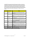
Table 3: RSG2100P Series Power terminal block connection description ......................................14
Table 4: RS232 over RJ45 console cable pin-out ...........................................................................19
Table 5: RJ45 Ethernet pin-out assignment ...................................................................................21
Table 6: RJ45 PoE pin-out assignment...........................................................................................21
Table 7: Cabling categories and 1000BaseTx compliance defined.................................................24
Table 8: Power Supply Specifications .............................................................................................27
Table 9: PoE Power Supply Specifications .....................................................................................27
Table 10: Failsafe Relay Contact Ratings .......................................................................................27
Table 11: Networking Standards Supported....................................................................................28
4
© 2008 RuggedCom Inc. All rights reserved Rev105