


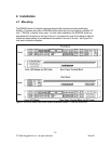
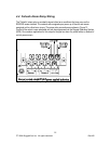

The RSG2100P can be equipped with either a Philips Screw Terminal Block or a Phoenix Plug
Terminal Block. The Philips Screw Terminal Block has Philips screws with a compression plate
allowing either bare wire connections or crimped terminal lugs. We recommend the use of #6 size
ring lugs to ensure secure, reliable connections under severe shock or vibration. Both terminal
blocks have a safety cover which must be removed via two Phillips screws before connecting any
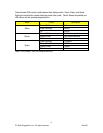
wires. The safety cover must be re-attached after wiring to ensure personnel safety. Refer to Table
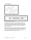
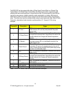
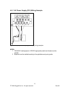
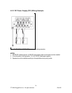
3 below for a description of each terminal as well as sections 4.2.1 through 4.2.2 for wiring
examples.
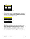
Terminal # Description Usage
1 PS1 Live / +
PS1 Live / + is connected to the positive (+) terminal if the
power source is DC or to the (Live) terminal if the power
source is AC.
2 PS1 Surge Ground
PS1 Surge Ground is connected to the Chassis Ground via
a jumper on the terminal block. Surge Ground is used as the
ground conductor for all surge and transient suppression
circuitry.
3 PS1 Neutral / -
PS1 Neutral / - is connected to the negative (-) terminal if
the power source is DC or to the (Neutral) terminal if the
power source is AC.
4 Chassis Ground
Chassis Ground is connected to the Safety Ground
terminal for AC inputs or the equipment ground bus for DC
inputs. Chassis ground connects to both power supply surge
grounds via a removable jumper.
5 PS2 +
PS2 + is connected to the positive (+) terminal of the 48VDC
power supply.
6 PS2 Surge Ground
PS2 Surge Ground is connected to the Chassis Ground via
a jumper on the terminal block. Surge Ground is used as the
ground conductor for all surge and transient suppression
circuitry.
7 PS2 -
PS2 - is connected to the negative (-) terminal of the 48VDC
power supply.
8 Relay NO Contact Normally open, failsafe relay contact.
9 Relay Common Failsafe relay common contact.
10 Relay NC Contact Normally closed, failsafe relay contact.
Table 3: RSG2100P Series Power terminal block connection description
14
© 2008 RuggedCom Inc. All rights reserved Rev105