


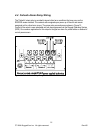
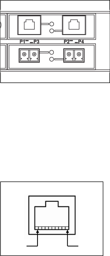
5 Ethernet Ports
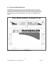
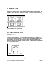
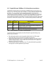
Each Ethernet module is equipped with two LEDs that indicate link/activity status information. The
LED will be solid for ports with link, and will blink for activity. The diagram in Figure 15 highlights
the port and the associated link/activity LED.
Figure 15: Ethernet panel LED description
Port 4 Port 3
Port 2 Port 1
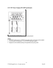
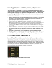
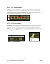
5.1 RJ45 Twisted-Pair Ports
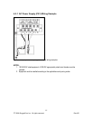
5.1.1 Data Ports
The RSG2100P may have several 10/100BaseTX ports that allow connection to standard CAT-5
UTP cable with RJ45 male connectors. All RSG2000 series RJ45 RuggedSwitch products feature
auto-negotiating, auto-polarity, and auto-crossover functions. The RJ45 receptacles can also
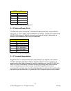
accept and take advantage of screened (commonly known as “shielded”) cabling. Figure 16 shows
the RJ45 port pins configuration.
Pin 1 Pin 8
Figure 16: RJ45 port pins configuration.
20
© 2008 RuggedCom Inc. All rights reserved Rev105