


5.2.2 Pluggable optics – Installation, removal, and precautions
The RSG2000 series of products can be ordered with pluggable optic form factors such as SFP
(Small Form-factor Pluggable) or GBIC (Gigabit Interface Converter) modules. These modules can
be safely inserted and removed while the chassis is powered and operating – this feature is also
known as “hot-swappable”. When inserting or removing optics there are several precautions that
should be taken. They include:
1. Ensuring that dust caps are mounted on SFP cages at all times unless a user is in the process
of inserting or removing an SFP module. The dust caps will prevent the accumulation of
residue or particles that may inhibit proper operation.
2. Ensuring that the user has properly discharged any possible electrostatic build-up and
electrostatic discharges (ESD). This can be accomplished by properly user ‘grounding’ via an
ESD wrist strap, or by touching earth or chassis ground before performing installation or
removal of optics. ESD can damage or shorten the life of optical modules when not plugged
into a chassis.
3. SFP and GBIC optical modules should always be stored in an ESD safe bag or other suitable
ESD safe environment, free from moisture and stored at proper storage temperature (–40 to
+85°C).
4. Disconnect all cables from SFP or GBIC module before insertion or removal of module.
5. Only RuggedCom Inc. certified optics should be used on RuggedCom products. Damage can
occur to optics and product if compatibility and reliability have not been properly assessed.
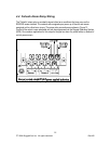
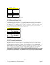
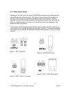
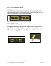
5.2.2.1 Module Insertion – GBICs and SFPs
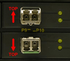
To insert GBICs or SFPs, special attention should be taken into the proper module orientation.
Refer to Figure 24 for proper module orientation, as ports on the upper row of the product require
optics to be inserted topside-up, and ports on the lower row of the product require modules to be
inserted topside-down. GBICs should be inserted with module dust cover in place. SFPs should
be inserted with dust cover in place, and the bail-latch in the locked position. Module should gently
slide into port and should lock in place when module is fully inserted. To protect optics, dust
covers should always be installed when cables are not connected.
Figure 24: SFP Orientation for top row and bottom row ports
25
© 2008 RuggedCom Inc. All rights reserved Rev105