


78
Chapter 7 Appendix
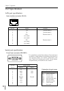
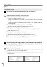
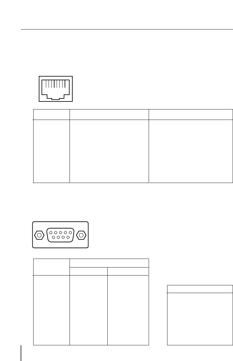
LAN port specification
Port Specification
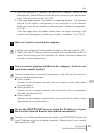
Serial port specification
pin No. Signal Function
1 TX+ Transfer data (+)
2 TX- Transfer data (-)
3 RD+ Receive data (+)
4 (not used)
5 (not used)
6 RD- Receive data (-)
7 (not used)
8 (not used)
12345678
8-pin modular connector (RJ-45)
D sub 9-pin connector (RS-232C)
Pin No. Signal Name
Socket Side A Side B
1CD -
2 RXD TXD
3 TXD RXD
4 DTR -
5 Ground Ground
6 DSR -
7 RTS -
8 CTS -
9- -
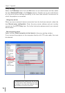
* It is possible to switch the polarity of the serial port
as shown in table below by switching the socket on
the network board. For further information, see
item "Serial Port Switching" (☞ p.65). At the factory
shipped setting, the socket is set to side A.
Function
CD Carrier detection
RXD Receive data
TXD Transfer data
DTR Data terminal ready
DSR Data set ready
RTS
Request to send
CTS Clear to send
- Not used
- Explanation of signal names
1234
9876
5