


Unit 3: Installation
SATO GT4xxe Series Operator Manual PN 9001138C Page 3-3
PRINTER INSTALLATION
This chapter provides guidance on how to station, connect, and load the printer once unpacked.
Following printer setup, procede to the next chapter for information on interface selection.
SITE LOCATION
• Stationed on a solid flat surface.
• Stationed away from hazardous materials.
• Stationed within operational distance of the host based on interface specifications.
CABLE CONNECTION
The procedure below provides instruction on typical cable connection. The same procedure will
apply to others that are not mentioned, but their connectors are also located behind the rear
housing cover.
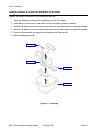
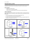
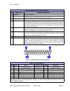
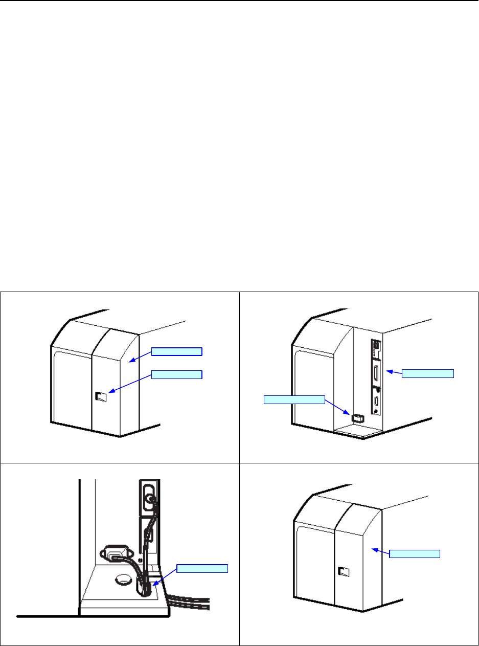
1 Press the rear housing ocver catch and remove laterally (Figure 3-2a).
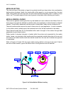
2 Locate and identify the required connectors (Figure 3-2b).
3 Connect the power supply and interface cables to their respective connectors (Figure 3-2c).
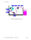
4 Replace rear housing cover (Figure 3-2d).
Figure 3-2a
Figure 3-2b
Figure 3-2c
Figure 3-2d
Rear Housing Cover
Housing Cover Catch
Interface Connectors
Power Supply Connector
Pull Prevention Slot
Rear Housing Cover