


Unit 4: Operation
SATO GT4xxe Series Operator Manual PN 9001138C Page 4-49
OPERATIONAL ADJUSTMENTS
These operational adjustments are for fine tuning the printer as necessary following the
configuration process and are largely confined to the four potentiometers located on the operator
panel. Refer to the table below for their function.
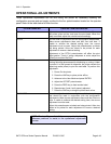
POTENTIOMETER DESCRIPTION/PROCEDURE
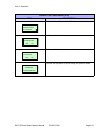
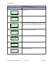
VOLUME Adjusts the audible decimal level for error indication. Power on
the printer, place on-line, and open the print head. When the
beep is emitted, adjust the volume level accordingly.
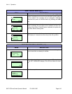
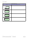
PITCH Is to be used in conjunction with the configuration adjustments.
Make course adjustments there and then fine tune here. If
unable to achieve the desired setting here, the course
adjustment must be reset. Adjust this potentiometer as labels
are being printed. Allow two labels to be printed for each
adjustment to ensure a desired setting.
Adjustment of the PITCH potentiometer will affect the print
offset postion. Thusly, if using a dispenser or cutter, adjust the
Offset first and then the Pitch.
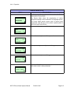
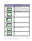
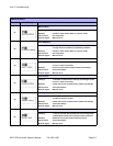
OFFSET The offset adjustment is used to reposition the media for
printing following advancement for dispensing or cutting. A label
is printed, it is fed forward for dispense, the printer retracts the
remaining media (offset) to print the next label. To preform this
adjustment:
1. Power On the printer.
2. Press the LINE key to place printer offline.
3. Advance to the User Mode and press ENTER.
4. Adjust the OFFSET potentiometer.
5. Press the FEED key to feed another label.
6. Repeat steps 3 and 4 until properly adjusted.
7. Press the LINE key to bring the printer back online.
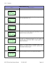
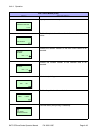
DARKNESS Is used to adjust the darkness or lightness of the printed image
and should be used in conjunction with the configuration
adjustments. Make course adjustments there and then fine tune
here. If unable to achieve the desired setting here, the course
adjustment must be reset.
Adjust this potentiometer as labels are being printed. Allow two
labels to be printed for each adjustment to ensure a desired
setting.
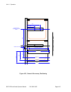
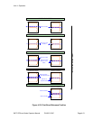
NOTE: The two Figures that follow are provided to identify
reference positions to assist in the operational adjustment
process.