


Data Exchange
890USE17700 April 2004 119
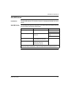
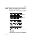
The Output Data
Process Image
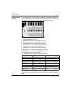
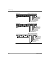
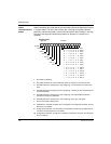
The output data process image contains the data written to the island from the
Modbus over TCP/IP host. This data is used to update the output modules on the
island bus. In the sample island bus assembly, there are four output modules—three
digital output modules and one analog output module.
Each digital output module uses one Modbus register for its data. The analog output
module requires two registers, one for each output channel. Therefore, a total of five
registers (registers 40001 through 40005) are needed to accommodate the four
output modules in the sample island bus assembly.
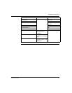
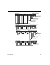
1 The value represented in register 40004 is in the range +10 to -10 V, with 11-bit resolution
plus a sign bit in bit 15.
2 The value represented in register 40005 is in the range +10 to -10 V, with 11-bit resolution
plus a sign bit in bit 15.
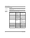
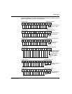
The digital modules use the LSBs to hold and display their output data. The analog
module uses the MSBs to hold and display its output data.
15 14 13 12 11 10 9 8 7 6 5 4 3 2 1 0
sign bit (see 2)
11-bit analog value (see 2)
ignored
15
14131211109 876 54 3210
register 40001 STB DDO 3200 data
register 40002 STB DDO 3410 data
15 14 13 12 11 10 9 8 7 6 5 4 3 2 1 0
register 40004
register 40005
STB AVO 1250 channel 2 data
15
14 13 12 11 10 9 8 7 6 5 4 3 2 1 0
ON/OFF conditions
of outputs 1 and 2
ON/OFF conditions
of outputs 1 ... 4
always 0
not used; always 0
register 40003 STB DDO 3600 data
15
14131211109 876 54321 0
ON/OFF conditions
of outputs 1 ... 6
always 0
sign bit (see 1)
11-bit analog value (see 1)
ignored
STB AVO 1250 channel 1 data