


Advanced Configuration Features
168
890USE17700 April 2004
The Island’s Process Image Blocks
Summary Two blocks of registers in the island’s data image (See The Data Image, p. 166) are
the focus for this discussion. The first block is the output data process image, which
starts at register 40001 and goes to register 44096. The other block is the input data
and I/O status process image, which also consumes 4096 registers
(45392 through 49487). The registers in each block are used to report island bus
device status and to dynamically exchange input or output data between the fieldbus
master and the island’s I/O modules.
Output Data
Process Image
The output data block (registers 40001 through 44096) handles the output data
process image. This process image is a Modbus representation of the control data
that has just been written from the fieldbus master to the NIM. Only data for the
island’s output modules is written to this block.
Output data is organized in 16-bit register format. One or more registers are
dedicated to the data for each output module on the island bus.
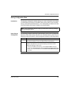
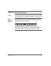
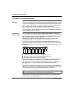
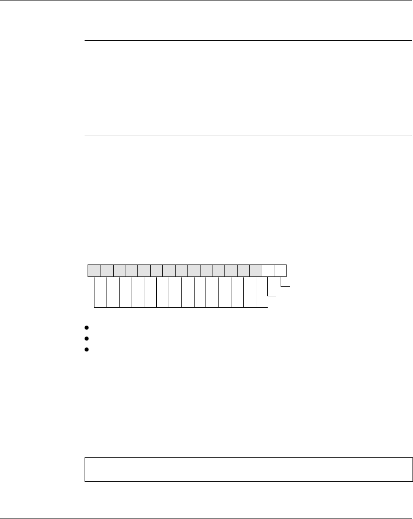
For example, say you are using a two-channel digital output module as the first
output module on your island bus. Output 1 is on and output 2 is off. This information
would be reported in the first register in the output data process image, and it would
look like this:
where:
Normally, a value of 1 in bit 0 indicates that output 1 is on.
Normally, a value of 0 in bit 1 indicates that output 2 is off.
The remaining bits in the register are not used.
Some output modules, such as the one in the example above, utilize a single data
register. Others may require multiple registers. An analog output module, for
example, would use separate registers to represent the values for each channel,
and might use the 11 or 12 most significant bits to display analog values in
IEC format.
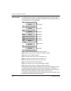
Registers are allocated to output modules in the output data block according to their
addresses on the island bus. Register 40001 always contains the data for the first
output module on the island—the output module closest to the NIM.
A detailed view of how the registers are implemented in the output data block is
shown in the process image example.
Note: The requirements of each output module in the Advantys STB family are described in
the Advantys STB Hardware Components Reference Guide (890 USE 172).
15
14 13 12 11 10
987654
3
210
1
0
always 0
register 40001 output data