


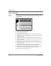
Connection Example
890USE17700 April 2004 145
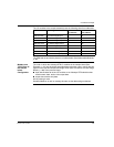
Output Process
Image
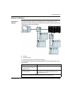
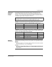
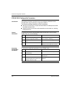
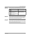
The I/O modules in the sample island bus assembly require five Modbus registers
in the output data image area (See The Output Data Process Image, p. 119). The
following table shows how these registers are organized:
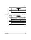
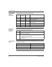
45407 N7 channel 2 status
AVI 1270 channel 2 status
45408 N8 channel 1 status
AVI 1250 channel 1 status
45409 N8 channel 2 status
AVI 1250 channel 2 status
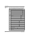
Modbus
Register
151413121110987654321 0
Modbus
Register
1514131211109876543210
40001 empty–set to 0 N2 data
STB DDI 3230 data
40002 empty–set to 0 N4 data
STB DDO 3420 data
40003 empty–set to 0 N6 data
STB DDO 3600 data
40004 N8 channel 1 data
STB AVO 1250, channel 1 data
40005 N8 channel 2 data
STB AVO 1250, channel 2 data