


CHEETAH 15K.7 FC PRODUCT MANUAL, REV. E 37
10.0 INSTALLATION
Cheetah 15K.7 FC disk drive installation is a plug-and-play process. There are no jumpers, switches, or terminators on the
drive. Simply plug the drive into the host’s 40-pin Fibre Channel backpanel connector (FC-SCA)—no cables are required.
See Section 11.5 for additional information about this connector.
Use the FC-AL interface to select drive ID and all option configurations for devices on the loop.
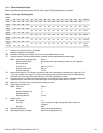
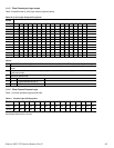
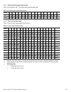
If multiple devices are on the same FC-AL and physical addresses are used, set the device selection IDs (SEL IDs) on the
backpanel so that no two devices have the same selection ID. This is called the hard assigned arbitrated loop physical
address (AL_PA). There are 125 AL_PAs available (see Table 27). If you set the AL_PA on the backpanel to any value other
than 0, the device plugged into the backpanel’s SCA connector inherits this AL_PA. In the event you don’t successfully
assign unique hard addresses (and therefore have duplicate selection IDs assigned to two or more devices), the FC-AL
generates a message indicating this condition. If you set the AL_PA on the backpanel to a value of 0, the system issues a
unique soft-assigned physical address automatically.
Loop initialization is the process used to verify or obtain an address. The loop initialization process is performed when power
is applied to the drive, when a device is added or removed from the Fibre Channel loop, or when a device times out
attempting to win arbitration.
• Set all option selections in the connector prior to applying power to the drive. If you change options after applying power to
the drive, recycle the drive power to activate the new settings.
• It is not necessary to low-level format this drive. The drive is shipped from the factory low-level formatted in 512-byte logi-
cal blocks. You need to reformat the drive only if you want to select a different logical block size.
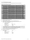
10.1 DRIVE ID/OPTION SELECTION
All drive options are made through the interface connector (J1). Table 24 provides the pin descriptions for the 40-pin Fibre
Channel single connector (J1).
10.2 DRIVE ORIENTATION
The drive may be mounted in any orientation. All drive performance characterizations, however, have been done with the
drive in horizontal (discs level) and vertical (drive on its side) orientations, which are the two preferred mounting orientations.
10.3 COOLING
The host enclosure must dissipate heat from the drive. You should confirm that the host enclosure is designed to ensure that
the drive operates within the temperature measurement guidelines described in Section 6.4.1. In some cases, forced airflow
may be required to keep temperatures at or below the temperatures specified in Section 6.4.1.
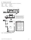
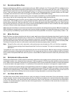
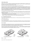
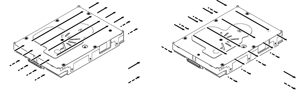
If forced air is necessary, possible air-flow patterns are shown in Figure 11. The air-flow patterns are created by fans either
forcing or drawing air as shown in the illustrations. Conduction, convection, or other forced air-flow patterns are acceptable
as long as the temperature measurement guidelines of Section 6.4.1 are met.
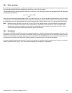
Figure 11. Air flow
Above unit
Under unit
e Air flows in the direction shown (back to front)
or in reverse direction (front to back)
Above unit
Under unit
e Air flows in the direction shown or
in reverse direction (side to side)