


CHEETAH 15K.7 FC PRODUCT MANUAL, REV. E 63
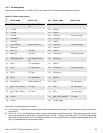
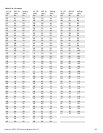
11.5.12 Device control codes
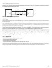
The drive inputs a Device Control Code on the DEV_CTRL_CODE lines at power up to determine the link rate on the Fibre
Channel ports. Both ports run at the same rate. If the backpanel does not connect to these lines, the drive has 10K ohm pull
up resistors that default the device control code to 7 (1.0625 GHz). Table lists the supported codes.
11.6 SIGNAL CHARACTERISTICS
This section describes the electrical signal characteristics of the drive’s input and output signals. See Table 24 on page 58
for signal type and signal name information.
11.6.1 TTL input characteristics
Table 29 provides the TTL characteristics.
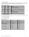
Table 28 Device control code values
2 (PIN 17) 1 (PIN 18) 0 (PIN 39) DEFINITION
0
0
0 Reserved for power failure warning.
0
0
1 Reserved for auto negotiation of link rate.
0
1
0 Reserved.
0
1
1 Reserved.
1
0
0 Reserved.
1
0
1 4.250 GHz operation on both ports.
1
1
0 2.125 GHz operation on both ports.
1
1
1 1.0625 GHz operation on both ports.
Table 29 TTL characteristics
STATE VOLTAGE CURRENT
Input high 1.9 < V
IH
< 5.5V I
IH
= ±500nA max.
Input low -0.5V < V
IL
< 0.9V I
OL
= ±500nA max.
Output high (-EN Bypass A, B) 2.4 < V
OH
< 5.25V I
OH
< -3mA
Output low (-EN Bypass A, B) V
OL
< 0.5V I
OL
< 3mA
Output high (-Parallel ESI) 2.4 < V
OH
< 0.9 V
CC
V
OH
> 0.9V
CC
I
OH
< -2.4mA
I
OH
< -500μA
Output low (-Parallel ESI) 0 < V
OL
< .45V I
OL
< 2.4mA
Output high (all other outputs) 2.4 < V
OH
< 0.9 V
CC
V
OH
> 0.9V
CC
I
OH
< -1.6mA
I
OH
< -500μA
Output low (all other outputs) 0 < V
OL
< .45V I
OL
< 1.6mA