


CHEETAH 15K.7 FC PRODUCT MANUAL, REV. E 61
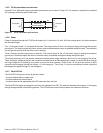
11.5.10 Motor start controls
The drive’s motor is started according to the Start_1 and Start_2 signals described in Table 26. The state of these signals can
be wired into the backplane socket or driven by logic on the backplane.
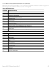
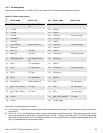
11.5.11 SEL_6 through SEL_0 ID lines
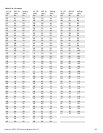
The SEL_6 through SEL_0 ID lines determine drive address, and, optionally, for an Enclosure Services Interface. When the
Parallel ESI line is high, the enclosure backpanel must provide address information on the SEL line. Refer to Table 27 for a
mapping of SEL to FC-AL physical addresses (AL_PA). You can think of the SEL lines as the equivalent of a backpanel logic
plug. The drives does not provide pull up resistors on these lines. The backpanel is required to provide high and low inputs to
the SEL_ID lines per the specifications in table 29 on page 63.
Note. Table 27 gives AL_PA values for each SEL value. The first entry in the table is SEL_ID 00. The last entry is
SEL_ID 7D. SEL_ID 7E is AL_PA 00 which is not valid for an NL_Port, so is not included in the table. Also,
SEL_ID 7Fh does map to a valid AL_PA; however, this value signals the drive that physical addresses are not
being assigned using the SEL lines and that a “soft” address will be determined by FC-AL loop initialization.
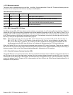
When the Parallel ESI line is low, the enclosure backpanel logic switches to ESI mode if supported. There are two modes of
ESI, seven bits of enclosure status and a bidirectional mode. ESI support and the mode are determined by the drive using a
discovery process. Refer to the Fibre Channel Interface Manual for a description of ESI operation.
11.5.11.1Parallel Enclosure Services Interface (ESI)
The parallel ESI line is an output from the drive. This line provides the enclosure with an indication of the present function of
the SEL lines. A high level, the default state, indicates the drive requires address information on the SEL lines. A low level
indicates the drive is attempting an ESI transfer. The enclosure may not support ESI on any or all drive locations. It may only
support the address function. Support of ESI is discovered by the drive. Refer to the Fibre Channel Interface Manual for a
description of ESI operations.
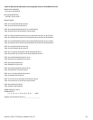
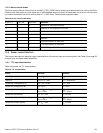
Table 26 Motor start control signals
CASE START_2 START_1 MOTOR SPIN FUNCTION
1 Low Low Motor spins up at DC power on.
2 High Low Motor spins up only when SCSI Start command is received.
3 Low High Motor spins up after a delay of 12 seconds times the modulo 8 value
of the numeric SEL ID of the drive from DC power on.
4 High High The drive will not spin up.