


-2
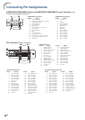
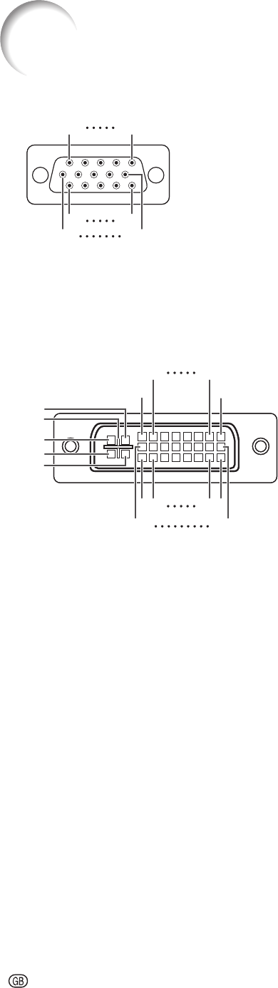
Connecting Pin Assignments
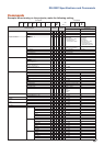
COMPUTER/COMPONENT input and COMPUTER/COMPONENT output Terminals: mini
D-sub 15 pin female connector
COMPUTER Input/Output COMPUTER Input/Output
Pin No. Signal Pin No. Signal
1.
2.
3.
4.
5.
6.
7.
8.
9.
10.
11.
12.
13.
14.
15.
Video input (red)
Video input (green/sync on green)
Video input (blue)
Not connected
Not connected
Earth (red)
Earth (green/sync on green)
Earth (blue)
Not connected
GND
Not connected
Bi-directional data
Horizontal sync signal: TTL level
Vertical sync signal: TTL level
Data clock
1.
2.
3.
4.
5.
6.
7.
8.
9.
10.
11.
12.
13.
14.
15.
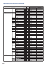
PR (CR)
Y
PB (CB)
Not connected
Not connected
Earth (PR)
Earth (Y)
Earth (PB)
Not connected
Not connected
Not connected
Not connected
Not connected
Not connected
Not connected
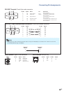
DVI-I Terminal: 29 pin connector
DVI Digital Input•
Pin No. Signal Pin No. Signal
1.
2.
3.
4.
5.
6.
7.
8.
9.
10.
11.
12.
13.
14.
15.
T.M.D.S data 2–
T.M.D.S data 2+
T.M.D.S data 2 shield
Not connected
Not connected
DDC clock
DDC data
Not connected
T.M.D.S data 1–
T.M.D.S data 1+
T.M.D.S data 1 shield
Not connected
Not connected
+5V power
Ground
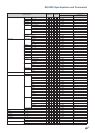
16.
17.
18.
19.
20.
21.
22.
23.
24.
C1.
C2.
C3.
C4.
C5.
Hot plug detection
T.M.D.S data 0–
T.M.D.S data 0+
T.M.D.S data 0 shield
Not connected
Not connected
T.M.D.S clock shield
T.M.D.S clock+
T.M.D.S clock–
Not connected
Not connected
Not connected
Not connected
Ground
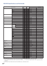
DVI Analog RGB Input• DVI Analog Component Input•
Pin No. Signal Pin No. Signal Pin No. Signal Pin No. Signal
1.
2.
3.
4.
5.
6.
7.
8.
9.
10.
11.
12.
13.
14.
15.
Not connected
Not connected
Not connected
Not connected
Not connected
DDC clock
DDC data
Vertical sync
Not connected
Not connected
Not connected
Not connected
Not connected
+5V power
Ground
16.
17.
18.
19.
20.
21.
22.
23.
24.
C1.
C2.
C3.
C4.
C5.
Hot plug detection
Not connected
Not connected
Not connected
Not connected
Not connected
Not connected
Not connected
Not connected
Analog input Red
Analog input Green
(Sync On Green)
Analog input Blue
Horizontal sync
(Composite Sync)
Ground
1.
2.
3.
4.
5.
6.
7.
8.
9.
10.
11.
12.
13.
14.
15.
Not connected
Not connected
Not connected
Not connected
Not connected
Not connected
Not connected
Not connected
Not connected
Not connected
Not connected
Not connected
Not connected
Not connected
Ground
16.
17.
18.
19.
20.
21.
22.
23.
24.
C1.
C2.
C3.
C4.
C5.
Not connected
Not connected
Not connected
Not connected
Not connected
Not connected
Not connected
Not connected
Not connected
Analog input Pr/Cr
Analog input Y
Analog input Pb/Cb
Not connected
Ground
5
10
15
1
11
6
5
10
15
1
11
6
17
24
1823
C3
2
1
9
16
C1
C2
C4
C5
87
17
24
1823
C3
2
1
9
16
C1
C2
C4
C5
87