WA_DEV_W218_PTS_002 Rev 005 Page 26 of 109
Product Technical Specification &
Customer Design Guidelines
Electrical Characteristics
Table 1. Input Power Supply Voltage
V
MIN
V
NOM
V
MAX
I
TYP.
I
MAX
Ripple max (U
ripp
)
VBATT
3.2(1)
3.6
4.8
1.35A
1.4A
10kHz to 100kHz: less
than100mVpp
greater than 100kHz: less
than 10mVpp
(1): This value has to be guaranteed during the burst (with 1.4A Peak in GSM or GPRS mode)
(2): Maximum operating Voltage Stationary Wave Ratio (VSWR) 1.5:1
When powering the WISMO218 with a battery, the total impedance (battery + protections + PCB)
should be less than 150m.
Pin Description
Table 2. Power Supply Pin Descriptions
Signal
Pin Number(s)
VBATT
29,30
GND
20,22,23,26,28,31
Application
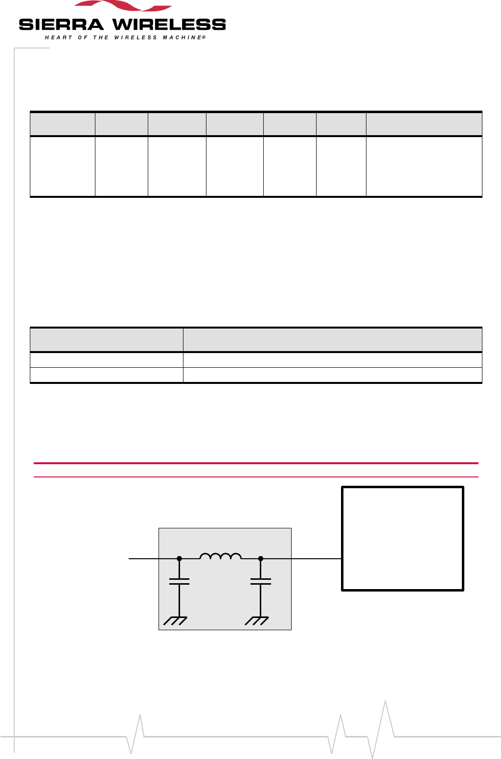
The reject filter can be connected between VBATT and the supply sources if the supply source is
noisy.
Caution: If the reject filter (C1+L1+C2) is an option, a capacitor (i.e. C2) is mandatory close to the VBATT.
Filter
WISMO218
Supply source
VBATT
L1
C1 C2
Figure 3. Reject Filter Diagram


