


WA_DEV_W218_PTS_002 Rev 005 Page 35 of 109
Product Technical Specification &
Customer Design Guidelines
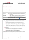
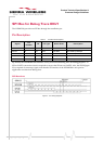
SPI Bus for Debug Trace ONLY
The WISMO218 provides one SPI bus through the castellation pin.
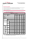
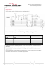
Pin Description
Table 6. SPI Bus Pin Descriptions
Signal
Pin
Number
I/O
I/O Type
Reset State
Description
SPI-CLK
15
O
2V8
Pull down
SPI Serial Clock
SPI-IO
13
I/O
2V8
Pull down
SPI Serial input/output
SPI-O
14
O
2V8
Pull down
SPI Serial input
~SPI-CS
17
O
2V8
Pull up
SPI Enable
SPI-IRQ
25
I
2V8
Pull down
SPI Interrupt
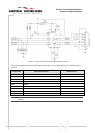
By default, the WISMO218 SPI interface is only used for monitoring trace for debug purposes. An
SPI-to-UART2 conversion circuit is required to convert the SPI trace to UART2. Also, the SPI-IRQ (pin
25) is required for interrupt. Again, note that the SPI interface of the WISMO218 is not open for
application use other than debug trace.
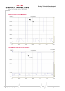
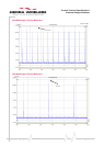
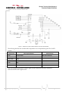
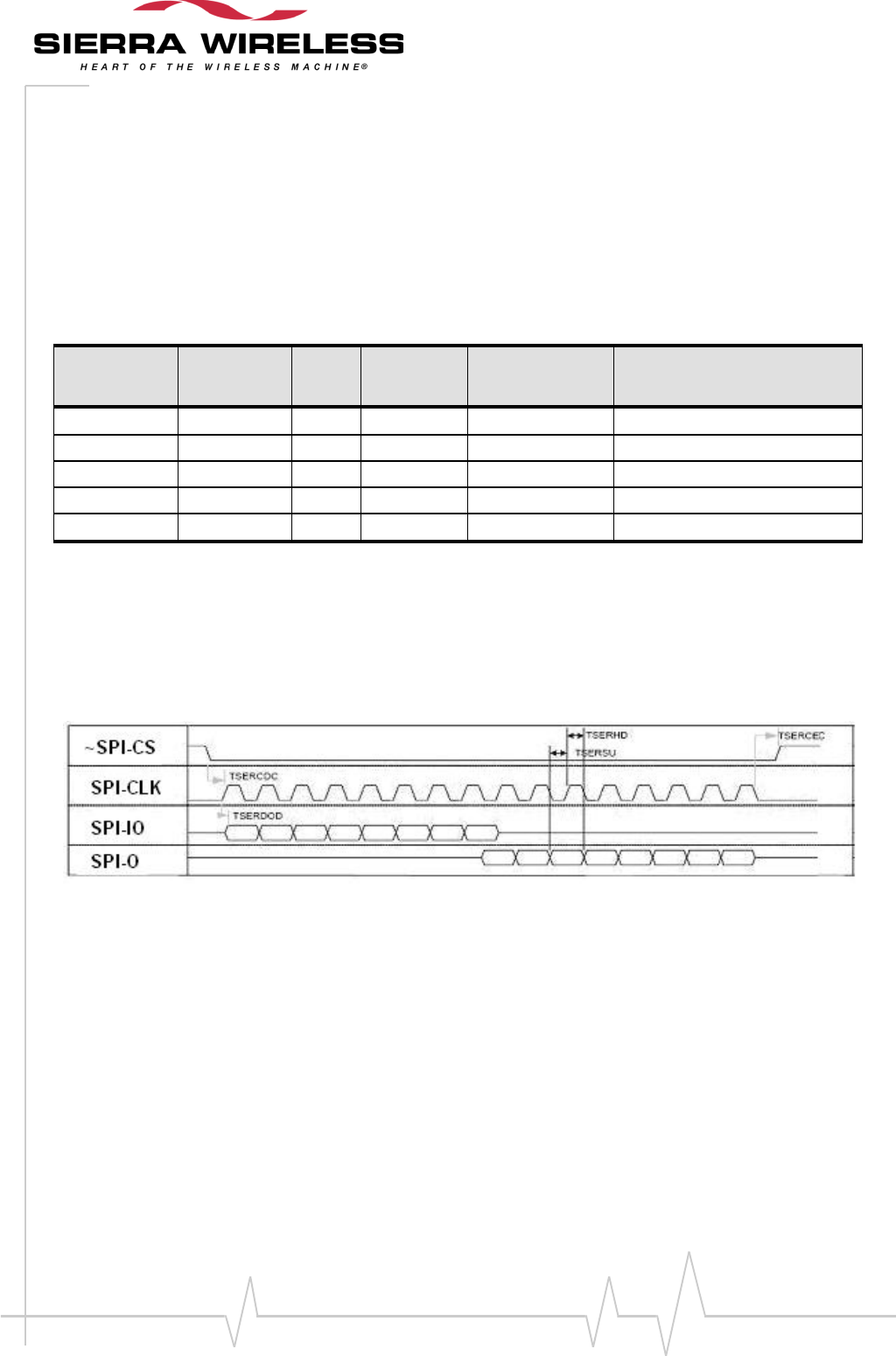
SPI Waveforms
Figure 4. SPI Timing Diagrams