


WA_DEV_W218_PTS_002 Rev 005 Page 62 of 109
Product Technical Specification &
Customer Design Guidelines
Pulse-Width Modulators (PWMs)
The WISMO218 contains two Pulse-Width Modulators (PWMs). They can be used in conjunction with
an external transistor for driving a vibrator, or a backlight LED.
Features
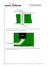
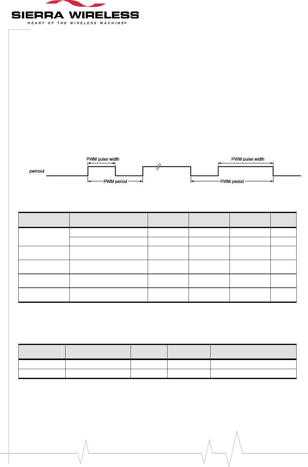
Each PWM uses two 7-bit unsigned binary numbers: one for the output period and one for the pulse
width or the duty cycle.
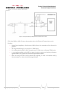
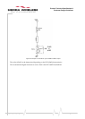
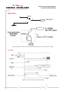
The relative timing for the PWM output is shown in the figure below.
Figure 25. Relative Timing for the PWM Output
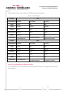
Table 21. PWM Electrical Characteristics
Parameter
Condition
Minimum
Typical
Maximum
Unit
V
OH
High impedance load
2.7
2.85
-
V
Load with I
oH
= 4mA
-
2.4
-
V
V
OL
-
-
-
0.1
V
I
PEAK
-
-
-
4
mA
Frequency
-
25.6
-
1083.3
kHz
Duty cycle
-
0*
-
100*
%
Pin Description
Table 22. PWM Pin Descriptions
Signal
Pin Number
I/O
I/O Type
Description
PWM0
36
O
2V8
PWM output
PWM1
35
O
2V8
PWM output
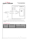
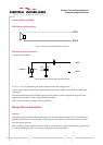
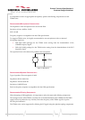
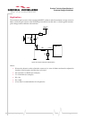
Application
Both the PWM0 and PWM1 signals can be used in conjunction with an external transistor for driving
a vibrator, or a backlight LED.