


WA_DEV_W218_PTS_002 Rev 005 Page 91 of 109
Product Technical Specification &
Customer Design Guidelines
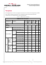
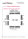
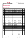
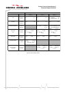
Castellation Pin
Pin-Out Description
Pin
#
Signal
Description
I/O
Pin
#
Signal
Description
I/O
1
SPKP
Speaker output positive
32 ohms
Analog
24
GPIO1
2.8V GPIO
I/O
2
SPKN
Speaker output
negative 32 ohms
Analog
25
SPI-IRQ
2.8V SPI interrupt
request input
I
3
MICP
Microphone input
positive
Analog
26
GND
Ground
Ground
4
MICN
Microphone input
negative
Analog
27
NC
Not connected
-
5
AUX_ADC0
Analog to digital
converter
I
28
GND
Ground
Ground
6
BAT-RTC
Power supply for RTC
backup
I
29
VBATT
Power supply
I
7
WISMO_READY
2.8V WISMO Ready
O
30
VBATT
Power supply
I
8
SIM-VCC
SIM power supply
O
31
GND
Ground
Ground
9
SIM-CLK
SIM clock
O
32
NC
Not connected
-
10
SIM-IO
SIM data
I/O
33
NC
Not connected
-
11
~SIM-RST
SIM reset
O
34
BUZZER
2.8V Buzzer PWM2
O
12
~RESET
input reset signal
I
35
PWM1
2.8V DC PWM 1
O
13
SPI-IO
2.8V SPI data input
I/O
36
PWM0
2.8V DC PWM 0
O
14
SPI-O
2.8V SPI data output
O
37
On/~OFF
Power On control
signal
I
15
SPI-CLK
2.8V SPI clock output
O
38
CT103/TXD*
2.8V UART1: Transmit
data
I
16
GPIO3
2.8V GPIO
I/O
39
~CT105/RTS*
2.8V UART1: Request
to send
I
17
~SPI-CS
2.8V SPI chip select
output
O
40
CT104/RXD*
2.8V UART1: Receive
data
O
18
TX_CTRL
2.8V TX Burst Indicator
O
41
~CT106/CTS*
2.8V UART1: Clear to
send
O
19
GPIO5
2.8V GPIO
I/O
42
~CT107/DSR
2.8V UART1: Data set
ready
O
20
GND
Ground
Groun
d
43
~CT109/DCD
2.8V UART1: Data
carrier detect
O
21
ANT
Radio antenna
connection
I/O
44
~CT108/DTR
2.8V UART1: Data
terminal ready
I
22
GND
Ground
Groun
d
45
~CT125/RI
2.8V UART1: Ring
indicator
O
23
GND
Ground
Groun
d
46
VCC_2V8
2.8V power supply
from module
O