


3.7
DAILY INSPECTION INSTRUCTIONS
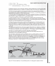
2 Inspect each length of source guide tube that will be used for cuts, inward dents and
heat damage. The inspection is primarily a visual one, but it should include the radiographer
using his hands to feel for the inward dents. This is necessary due to the fact the outer
material of the source guide tube is a flexible waterproof material that can mask dents.
During a visual-only inspection, a dent in the source guide tube may retain a circular
appearance on the exterior, while having an inward dent in the metallic conduit directly
below the waterproof material. This type of masked dent can be felt by the radiographer's
hands. Dents in the source guide tubes are the major cause of source hang-ups.
3 Inspect the attachment of the collimator to the source stop (exposure head) if used
during radiography.
Daily inspection of the remote controls
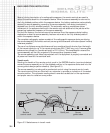
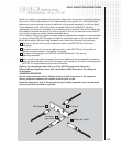
The remote control consists of a control crank, a control cable with a connector swaged at
one end, two control cable conduits and a connector plug assembly.
The control crank contains a diagonally cut, geared drive wheel that matches the outer
helical winding of the control cable. This worm-gear arrangement of the control crank drive
wheel and the control cable provides the radiographer with a reliable means to project and
retract the source assembly from and to the exposure device. The control crank is equipped
with a lever brake that retains the source assembly while in the exposure head. Beneath the
control crank is a label that indicates the direction for EXPOSE and RETRACT during use in
addition to ON and OFF positions for the brake. Control cranks are available with an
odometer to provide the radiographer with the approximate travel distance of the source
assembly. The travel distance is indicated in increments of feet and tenths of a foot.
Radiographers can count the number of rotations of the crank handle when using control
cranks that are not equipped with odometers to obtain an approximation of the travel distance.
One full revolution of the crank handle is equal to approximately 10in (25.4cm) of travel.
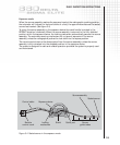
Two remote control conduits (sheaths, housings) are attached to the control crank.
One conduit contains the working side of the control cable that drives the source assembly
out of the exposure device and through the source guide tubes. The second conduit is the
reserve conduit containing the length of the control cable necessary for projection of the
source assembly. The remote control conduits provide a degree of protection of the control
cable against the elements common to the working environments that industrial
radiography is performed.
Attached to the opposite end of the remote control conduits is a connecting plug assembly
that is used for attachment of the remote controls to the locking mechanism of the
exposure device. The connecting plug assembly and the control cable connector are
designed with minimal tolerances. A connection of the source assembly connector to the
control cable connector must be completed before the remote control connecting plug
assembly can be attached to the locking mechanism of the exposure device. A protective
end-cover must be installed after use of the remote controls. The protective cover provides
protection to the connecting plug assembly and the control cable connector and prevents
the ingress of water, mud, sand or other foreign matter.
The control cable (drive cable) is a flexible, carbon steel cable with an outer helical winding.
The length of control cable is approximately twice the length of the remote controls.
Attached to one end of the control cable is a male connector. The control cable when used
in conjunction with the remote control as a system provides a positive mechanical control of
the source assembly at a distance. The control cable is a critical link for safe operation and is
the radiographer's only means of control over the source assembly. Therefore, the control
cable's storage, use, daily inspection and quarterly maintenance are critical elements to the
prevention of a control cable failure. In almost all cases, repairs for a control cable are not
possible, with the exception of replacing the control cable's Model 550 male connector every
five years. Damaged or defective control cables must not be used and removed from service.