


4.7
MAINTENANCE INSTRUCTIONS
5 Begin assembly of the locking mechanism by lightly coating all components with
MIL-G-23827B or C, MIL-PRF-23827C grease. Treat all screw thread ends with Vibratite™ or
Locktite™ thread sealant.
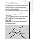
Mount the locking mechanism plate horizontally in a vise or fixture with the plunger lock
and retainer at a 12 o'clock position. (Note: carefully mount the locking mechanism plate in
a vise or fixture so hands are free for the assembly procedure and no damage to the mount
plate will occur.)
The narrow end of the lock slide slot must be located at the 3 o'clock position. Locate the
lock slide and return spring into the mating slot of the selector body.
Place the selector ring with the word CONNECT at the 12 o'clock position, over the selector
body. Push the lock slide inward during placement of the selector ring for clearance.
Doing so will allow the selector ring to rest flush on the selector body. Insert the anti-
rotation lug springs at the top and bottom of the selector body. Place the anti-rotation
lugs over the springs.
Place the tungsten sleeve with the large diameter facing downward, on the center of the
lock slide. Place the compression spring over the sleeve.
Install the selector ring retainer into the selector ring. Verify that the three non-threaded
holes line up under the word CONNECT located on the selector ring. Depress the selector
ring retainer into the selector ring until it is flush with the top of the selector ring. Hold
the selector ring retainer firmly against the mounting plate until the 10-32 x 1
1
/
4in screws
are installed.
While firmly holding the locking mechanism against the mounting plate, turn the plate over
to expose the back side of the mounting plate. Install the four 10-32 x 1
1
/
4in socket head
screws to secure the mechanism to the mounting plate. Torque the socket head screws to
30in/lb (3.39Nm) + or - 5in/lb (0.57Nm) using a calibrated torque wrench.
6 Perform functional safety testing of the locking mechanism by the following:
Mount the locking mechanism plate vertically in a vise or mounting fixture with the plunger
lock at the 12 o'clock position.
Insert the ‘U- tool’ into the top and bottom holes of the selector assembly and rotate the
selector ring toward the OPERATE position.
Push the lock slide until the sleeve snaps into place.
While in the OPERATE position, wind out a short length of control cable and pass it through
the front of the selector assembly. Attach a mock source assembly or the test jumper
connector to the control cable connector and withdraw it into the selector assembly.
Pull on the section of control cable and confirm that the lock slide automatically secures the
connector. The lock slide must snap shut in a fast and smooth motion when triggered.
Verify the securement action of selector mechanism by attempting to both push and
pull the mock source assembly out of the selector mechanism while in the EXPOSE, LOCK
and CONNECT positions.