3.9
DAILY INSPECTION INSTRUCTIONS
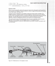
Ball diameter 1 2 Ball shank
3 Female slot width
Connector 4
gap width
Check for freedom of movement of the control cable within the remote controls by moving
the control crank handle back and forth approximately one-quarter turn. During this test,
take care to avoid cranking the control cable onto the ground exposing it to dirt and sand.
If any resistance is felt during this check, re-inspect the control conduits for dents or
depressions. If dents are not present on the remote control conduits, the control cable may
be rusted stiff somewhere within the control conduits. Do not use remote controls that do
not function properly or exhibit defects described above.
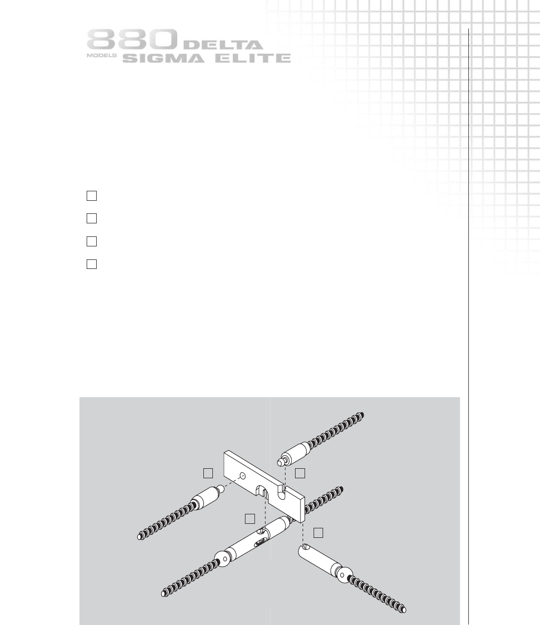
A final check of the control cable connector and source assembly connector is accomplished
by use of a Model 550 NO GO gauge to check for significant wear on the connectors that
would affect safety. Without using excessive force, check the following four positions:
1 The ball at the end of the control cable connector must NOT GO into the hole of
the gauge.
2 The shank or stem of the control cable connector must NOT GO into the smaller of
the two notches located on the side of the gauge.
3 The width of the gauge must NOT GO into the female slot of the source
assembly connector.
4 After a positive connection between the control cable and source assembly connectors
has been accomplished, verify that the larger notch located on the side of the gauge will
NOT GO in the gap between the joined connectors.
Replace any components that fail any of the NO GO gauge tests, because a
failure indicates significant wear that could allow safety features of the design to
be defeated.
IMPORTANT REMINDER
Do not compromise on safety. Always perform a daily inspection of the exposure
device, projection sheaths and remote controls prior to use.
Defective equipment that is discovered during the daily inspection must be removed
from service until repaired or replaced.


