


3-17
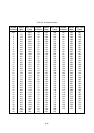
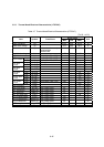
3.5.3 Thermal Head Electrical Characteristics (LTPF247)
Table 3-7 Thermal Head Electrical Characteristics (LTPF247)
(Ta=25 ± 10°C)
Rated value
Item Symbol Conditions
MIN TYP MAX
Unit
Head resistance RH 630.5 650 669.5 Ω
Head drive voltage Vp 21.6 24.0 26.4 V
Head drive current Ip At max. simultaneously
activated dots
number=248
− 9.2 10.4 A
Logic block voltage Vdd 4.75 5.00 5.25 V
Logic block current Idd fCLK=8MHz,fDI=1/2fCLK −− 64 mA
"High" VIH CLK,DAT,LATCH,DST 0.8×Vdd − Vdd V
Input voltage
"Low" VIL CLK,DAT,LATCH,DST 0 − 0.2×Vdd V
"High" IIH DAT VIH = 5V −− 0.5 µA
DAT
input
current
"Low" IIL DAT VIL = 0V −−−0.5 µA
"High" IIH DST −−120 µA
DST
input
current
"Low" IIL DST −−−2.0 µA
"High" IIH CLK −−2.0 µA
CLK
input
current
"Low" IIL CLK −−−2.0 µA
"High" IIH LAT −− 2.0 µA
LATCH
input
current
"Low" IIL LAT −−−2.0 µA
"High" VDOH OPEN state, Vdd =4.5V 4.45 −−µA
DAT
output
current
"Low" VDOL −−0.05 µA
CLK frequency f CLK −− 4MHz
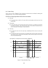
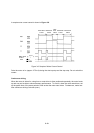
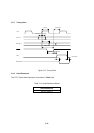
CLK pulse width tw CLK See Timing Chart 35 −−ns
DAT setup-time tsetup DI See Timing Chart 30 −−ns
DAT hold time thold DI See Timing Chart 10 −−ns
DAT out delay time td DO See Timing Chart −−120 ns
LATCH pulse width tw LAT See Timing Chart 100 −−ns
LATCH setup time tsetup LAT See Timing Chart 200 −−ns
LATCH hold time thold LAT See Timing Chart 50 −−ns
DST setup time tsetup DST See Timing Chart 300 −−ns
Output delay time tDo See Timing Chart −− 10 ns