


3-18
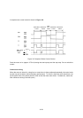
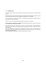
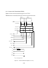
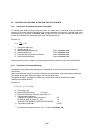
3.5.4 Structure of the Thermal Head (LTPF347)
Figure 3-11 shows the thermal head block diagram for the LTPF347.
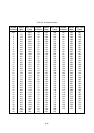
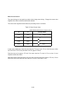
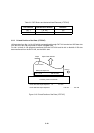
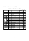
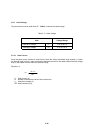
Table 3-8 shows the relationship between DST blocks and activated heat elements.
Figure 3-11 Thermal Head Block Diagram (LTPF347)
DAT IN2
CLK
LATCH
DST2
DAT OUT2
TH
TH
Vdd
GND
Output driver
Latch register
Shift register
Heat elements
Vp
DOT640
DOT385
DOT384
DOT1
Thermistor
Block 2 Block 1
DAT IN1
DAT OUT1
*1
*1
N.C. if not using DAT OUT
DST1
*1