


1.4 About the product
Chapter 1: Overview 7
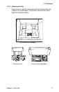
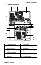
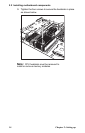
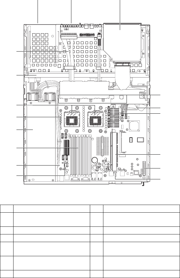
1.4.3 System internal views
1 Floppy disk drive bay 8 FDD connector
2 LED control board 9 Power connector (located
underneath the cabling)
3 Slim CD-ROM drive 10 Memory slots
4 Fan bracket 11 EPS 12V 500W power supply
5 IDE connector (located under-
neath the fan bracket)
12 Processor sockets
6 Fan connectors 13 1-port S-ATA backplane
board x 2pcs
7 Riser card 14 Front panel cables
7
6
12 3
4
5
6
8
9
6
10
11
12
6
13
14