


ELECTRICAL SPECIFICATION SSD-DXXX(I)-4300 DATA SHEET
SILICONSYSTEMS PROPRIETARY
This document and the information contained within it is confidential and proprietary to SiliconSystems, Inc.
All unauthorized use and/or reproduction is prohibited.
4300D-00DSR PAGE 13 FEBRUARY 27, 2009
AC CHARACTERISTICS
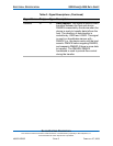
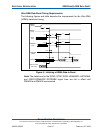
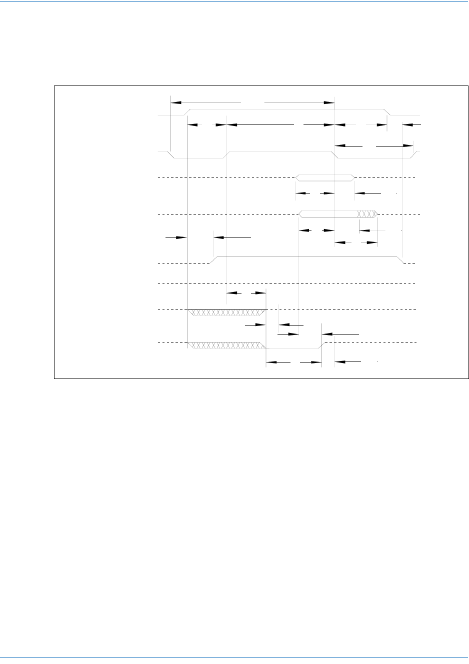
True IDE PIO Mode Read/Write Access Timing
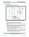
Figure 4: True IDE PIO Mode Read/Write Access Timing Diagram
Notes:
1. The device address consists of -CS0, -CS1, and A[02::00].
2. The data consists of D[15::00] (16-bit) or D[07::00] (8 bit).
3. -IOCS16 is shown for PIO modes 0, 1, and 2. For other modes, this signal is
ignored.
4. The negation of IORDY by the device is used to extend the PIO cycle. The
determination of whether the cycle is to be extended is made by the host
after t
A
from the assertion of -IORD or -IOWR. The assertion and negation
of IORDY is described in the following three cases:
a. The device never negates IORDY; no wait is generated.
b. The device starts to drive IORDY low before t
A
, but causes IORDY to be
asserted before t
A
; no wait generated.
c. The device drives IORDY low before t
A
; wait generated. The cycle
completes after IORDY is reasserted. For cycles where a wait is
generated and -IORD is asserted, the device places read data on D15-
D00 for t
RD
before causing IORDY to be asserted.
t
1
t
2
t
9
t
3
t
4
t
2i
t
7
t
A
t
C
t
RD
t
C
t
B
t
5
t
6
t
6z
-IORD / -IOWR
Write
Data (D15:D00)
(See note 2)
Read
Data (D15:D00)
(See note 2)
ADDR valid
(A02, A01, A00, -CS0, -CS1)
(See note 1)
t
8
t
0
IORDY
(See note 4, 4-1)
IORDY
(See note 4, 4-2)
IORDY
(See note 4, 4-3)
-IOCS16
(See note 3)
(See note 4a)
(See note 4b)
(See note 4c)
(See note 2)
(See note 2)
(See note 1)