


ATA COMMAND BLOCK AND SET DESCRIPTION SSD-DXXX(I)-4300 DATA SHEET
SILICONSYSTEMS PROPRIETARY
This document and the information contained within it is confidential and proprietary to SiliconSystems, Inc.
All unauthorized use and/or reproduction is prohibited.
4300D-00DSR PAGE 41 FEBRUARY 27, 2009
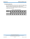
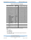
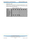
* = This function does not apply to SiliconDrive IIs that have DMA disabled.
Notes:
• CY = Cylinder
• SC = Sector Count
• DH = Drive/Head
• SN = Sector Number
• FR = Feature LBA — LBA bit of the Drive/Head register (D denotes that
only the drive bit is used)
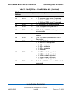
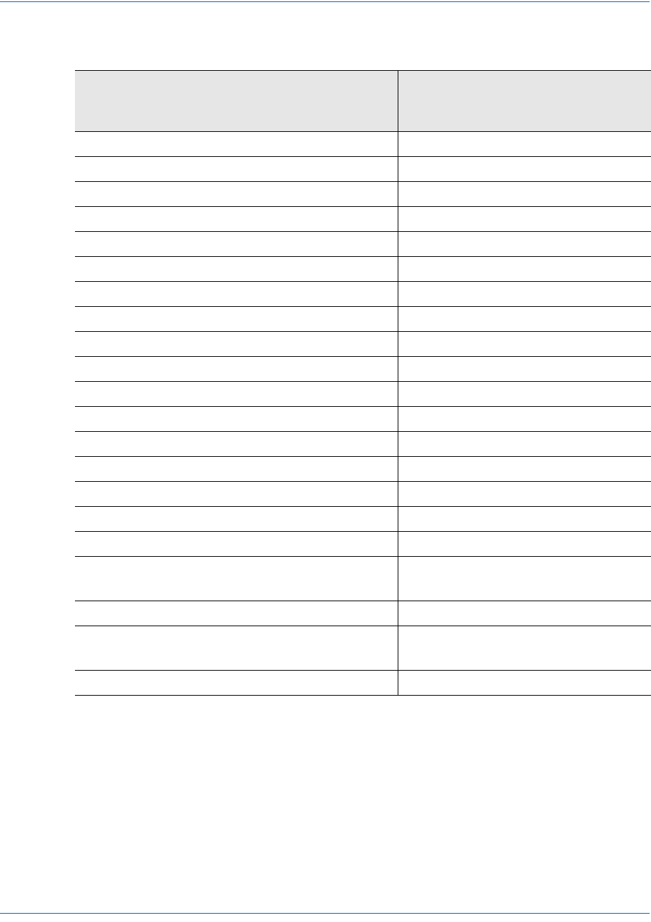
1 Read Long Sector 22h, 23h - - Y Y Y Y
1 Read Sector(s) 20h, 21h - - Y Y Y Y
1 Read Verify Sector(s) 40h, 41h - Y Y Y Y Y
1 Recalibrate 1Xh - - - - Y -
1 Request Sense 03h - - - - D -
1 Seek 7Xh - - YYYY
1 Set Features EFh Y - - D -
1 Set Multiple Mode C6h - Y - - D -
1 Set Sleep Mode 99h, E6h - - - - D -
1 Standby 96h, E2h - - - - D -
1 Standby Immediate 94h, E0h - - - - D -
1 Translate Sector 87h - YYYYY
1 Wear Level F5h - - - - Y -
2 Write Buffer E8h - - - - D -
1 Write DMA* CAh - YYYYY
2 Write Long Sector 32h, 33h - Y Y Y Y
3 Write Multiple C5h - Y Y Y Y Y
3 Write Multiple w/o
Erase
CDh - YYYYY
2 Write Sector(s) 30h, 31h- YYYYY
2 Write Sector(s) w/o
Erase
38h - YYYYY
3 Write Verify 3Ch - YYYYY
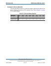
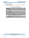
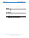
Table 28: ATA Command Set (Continued)
Class Command Name
Command
Code
Registers Used
FR SC SN CY DH LBA