


Si53xx-RM
Rev. 0.5 49
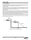
5.2.3. Jitter Tolerance
Jitter tolerance is defined as the maximum peak-to-peak sinusoidal jitter that can be present on the incoming clock
before the DSPLL loses lock. The tolerance is a function of the jitter frequency, because tolerance improves for
lower input jitter frequency.
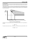
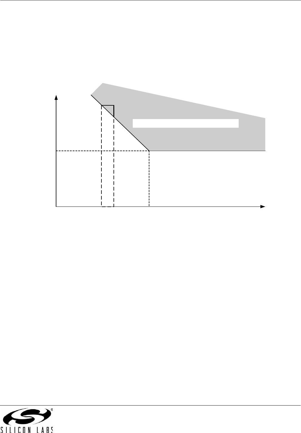
The jitter tolerance of the DSPLL is a function of the loop bandwidth setting. Figure 23 shows the general shape of
the jitter tolerance curve versus input jitter frequency. For jitter frequencies above the loop bandwidth, the tolerance
is a constant value A
j0
. Beginning at the PLL bandwidth, the tolerance increases at a rate of 20 dB/decade for
lower input jitter frequencies.
Figure 23. Jitter Tolerance Mask/Template
The equation for the high frequency jitter tolerance can be expressed as a function of the PLL loop bandwidth (i.e.,
bandwidth):
For example, the jitter tolerance when f
in
= 155.52 MHz, f
out
= 622.08 MHz and the loop bandwidth (BW) is 100 Hz:
Input
Jitter
Amplitude
A
j0
–20 dB/dec.
f
Jitter In
Excessive Input Jitter Range
BW/100 BW/10
BW
A
j0
5000
BW
-------------
ns pk-pk=
A
j0
5000
100
-------------
50 ns pk-pk==