


Si53xx-RM
80 Rev. 0.5
calibration and will appear after the self-calibration routine is completed. The SQ_ICAL bit is self-clearing after a
successful ICAL.
After a successful self-calibration has been performed with a valid input clock, it is not necessary to reinitiate a self-
calibration for subsequent losses of input clock. If the input clock is lost following self-calibration, the device enters
digital hold mode. When the input clock returns, the device relocks to the input clock without performing a self-
calibration.
After power-up and writing of dividers or PLL registers, the user must set ICAL = 1 to initiate a self-calibration. LOL
will go low when self calibration is complete. Depending on the selected value of the loop bandwidth, it may take a
few seconds more for the output frequency and phase to completely settle.
It is recommended that a software reset precede all ICALs and their associated register writes by setting
RST_REG (Register 136.7).
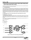
7.2.1.1. PLL Self-Calibration (Si5324, Si5327, Si5369, Si5374)
Due to the low loop bandwidth of the Si5324, Si5327, Si5369, and Si5374, the lock time of the Si5324/27/69/75 is
significantly longer than the lock time of the Si5326. As a method of reducing the lock time, the FAST_LOCK
register bit can be set to improve lock times. As the Si5324/27/69/74 data sheets indicate, FAST_LOCK is the LSB
of register 137. When FAST_LOCK is high, the lock time decreases. Because the Si5324/27/74 is initialized with
FAST_LOCK low, it must be written before ICAL is set. Typical Si5324/27/69/74 lock times (as defined from the
start of ICAL until LOL going low) with FAST_LOCK set are one to two seconds. To further reduce lock times, it is
also recommended that a value of 001 be written to LOCKT (the three LSBs of register 19).
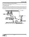
7.2.2. Input Clock Stability during Internal Self-Calibration
An ICAL must occur when the selected active CKINn clock is stable in frequency and with a frequency value that is
within the operating range that is reported by DSPLLsim. The other CKINs must be stable in frequency (< 100 ppm
from nominal) or squelched during an ICAL.
7.2.3. Self-Calibration Caused by Changes in Input Frequency
If the selected CKINn varies by 500 ppm or more in frequency since the last calibration, the device may initiate a
self-calibration.
7.2.4. Narrowband Input-to-Output Skew (Si5319, Si5324, Si5326, Si5327, Si5368, Si5369, Si5374, Si5375)
The input-to-output skew is not controlled. External circuitry is required to control the input-to-output skew. Contact
Silicon Labs for further information.
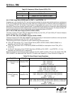
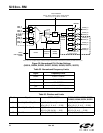
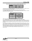
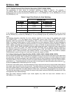
7.2.5. Clock Output Behavior Before and During ICAL
Table 37. CKOUT_ALWAYS_ON and SQ_ICAL Truth Table
Cases CKOUT_ALWAYS_ON SQ_ICAL Results
1
1
0 0 CKOUT OFF until after the first ICAL
2
2
01
CKOUT OFF until after the first successful
ICAL (i.e., when LOL is low)
3
3
1 0 CKOUT always ON, including during an ICAL
4
4
11
CKOUT always ON, including during an ICAL.
Use these settings to preserve output-to-output
skew
Notes:
1. Case 1 should be selected when an output clock is not desired until the part has been initialized after power-up, but is
desired all of the time after initialization.
2. Case 2 should be selected when an output clock is never desired during an any ICAL. Case 2 will only generate
outputs when the outputs are at the correct output frequency.
3. Case 3 should be selected whenever a clock output is always desired.
4. Case 4 is the same as Case 3.